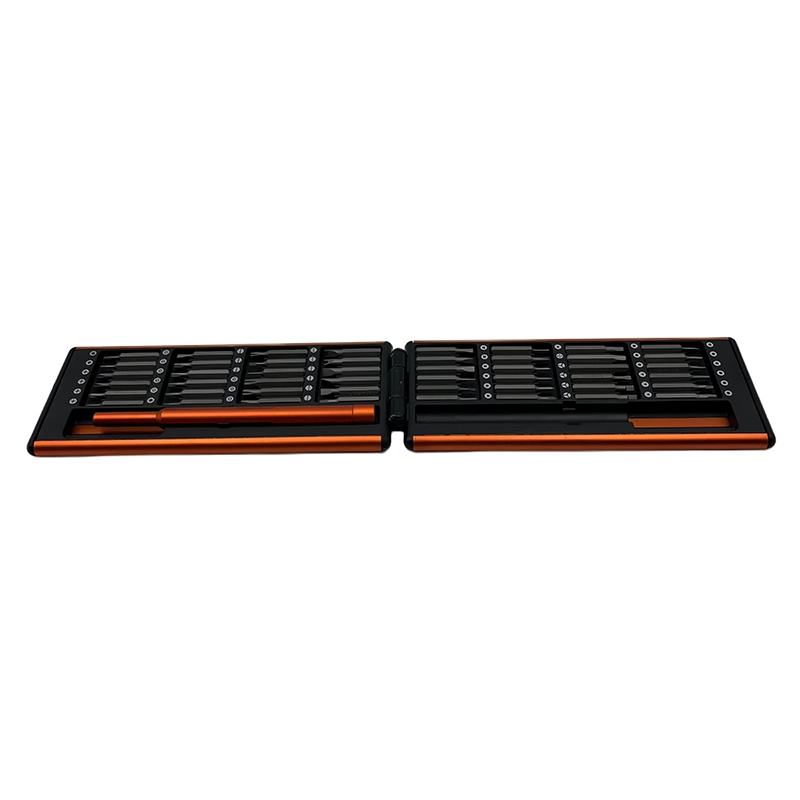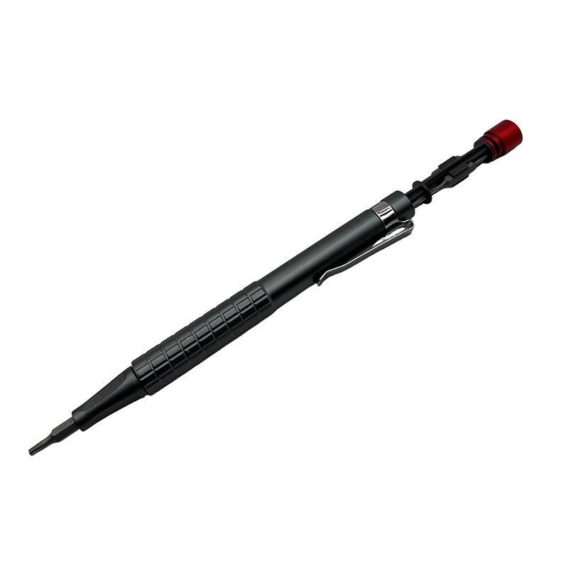
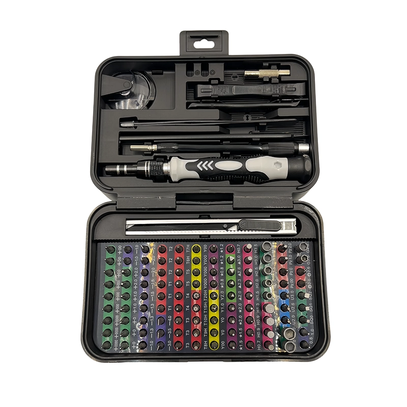
For MIDI-controller knob and potentiometer faceplate service, confirm the exact product, authorized service boundary, safe power state and fastener map before selecting a bit. Support the assembly, use a full-fitting tip, preserve each screw position and rebuild the non-fastener stack before seating hardware. Stop when fit, alignment or resistance changes, then verify every affected function through the maker's documented process.
MIDI-controller knob and potentiometer faceplate service manual screwdriver workflow
MIDI-controller knob and potentiometer faceplate service manual screwdriver workflow is a controlled process for defining the service boundary, matching a full-fitting bit, recording every hardware layer, rebuilding the complete joint stack, recognizing a stop condition and verifying affected functions without using extra hand force as a substitute for model-specific instructions.
What customer problem does MIDI-controller knob and potentiometer faceplate service actually solve?
How can worn MIDI-controller knobs and potentiometers be inspected while protecting the printed faceplate from driver, nut and washer marks? That question is narrower and more useful than asking whether a large manual screwdriver set can “repair” the entire product category. The fastener task begins only after the owner or technician has identified the model, preserved data where relevant and separated a mechanical joint from an electrical, optical, battery or software fault. Write the present symptom and the expected post-service check before choosing a bit. This prevents a visible screw from becoming a false diagnosis and gives the final inspection a clear purpose.
Focus on front-panel maintenance: knob removal, shaft inspection, panel-nut control and access to a documented replaceable control. This is not a PCB assembly guide, a soldering tutorial or proof that an electrical symptom comes from the potentiometer rather than firmware, wiring or signal routing. This boundary matters in European and North American repair markets because a product can contain ordinary screws beside parts that demand training, controlled disposal, calibration or maker authorization. A manual tool improves tactile feedback; it does not remove those obligations. If the current instructions, parts status or hazard controls do not support the requested operation, the honest answer is to stop or narrow the task rather than invent a broadly compatible repair route.
What preparation makes MIDI-controller knob and potentiometer faceplate service repeatable?
Disconnect USB and any external power, photograph every knob pointer against its scale and cover the surrounding finish with a clean removable mask. Label knob types, measure exposed shaft height and map only the rear screws needed to reach the control body. Preparation produces the reference needed for reassembly and for another person to audit the work. Take orientation photographs as well as close details, assign each fastener a position and keep hardware from adjacent modules in different rows. If the product has several revisions, use the full identifier rather than the retail family name. Revision mistakes create more rework than a small difference in the number of bits carried in the case.
Build the bench around the actual hazards and loose-part size. A stable padded fixture keeps the driver hand from also holding the product, while raking light reveals recess fit and trapped materials. Apply ESD controls around exposed boards and preserve the manufacturer's battery, mains, optical, adhesive and data rules. For MIDI-controller knob and potentiometer faceplate service, decide where the part will rest after its last screw is removed; that simple choice prevents cables, springs and unsupported covers from becoming the next failure.
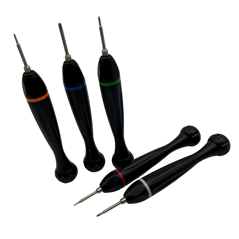
Which manual bit and handle fit MIDI-controller knob and potentiometer faceplate service?
For MIDI-controller knob and potentiometer faceplate service, start with the actual fastener, not a size remembered from a similar device. Clean and illuminate the recess, compare likely profiles under magnification and choose the tip that fills the shape at full depth with minimal rotational play. Confirm that the bit shoulder and holder clear surrounding surfaces through the useful turn. A longer bit helps only when it stays square; otherwise extra reach becomes extra lean and places one edge of the recess under a damaging load.
Handle diameter controls how quickly finger force becomes torque. For MIDI-controller knob and potentiometer faceplate service, a modest grip and free rotating cap usually make alignment easier than a high-leverage handle. Use enough downward force to keep a fully fitted bit seated, but never use pressure to compensate for a rocking tip. Magnetism may retain ferrous screws, yet it should be evaluated around sensors, magnets and loose metal. Record profile, working length, holder play and the stop response as one selection decision.
How is the fastened stack arranged in MIDI-controller knob and potentiometer faceplate service?
A knob may cover a shaft, bushing, cosmetic washer and thin retaining nut above printed legends or a brushed faceplate. The control body behind the panel must be supported so nut rotation does not twist wires, while nearby encoder caps can look similar but use a different removal method. Treat that arrangement as a stack rather than a group of independent screws. Locators, washers, contacts, seals, spacers, films, cables and moving pieces establish the geometry before a fastener adds clamp load. Photograph the untouched stack from more than one angle and note which parts become free after each layer is removed. A two-dimensional tray is useful, but a layer label and removal step make it much harder to return a familiar-looking screw to the wrong depth.
During MIDI-controller knob and potentiometer faceplate service, observe what carries load and what merely covers or guides another part. The correct bit can still cause damage if the workpiece bends, the shaft touches an edge or the operator uses the screw to pull two misaligned components together. Place support near the joint, leave the second hand free to control the released part and keep magnetic pickup, loose hardware and metal debris appropriate to the electronics around the work zone.
What removal sequence controls MIDI-controller knob and potentiometer faceplate service?
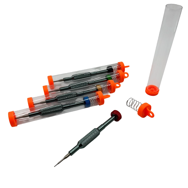
Lift each documented push-fit or set-screw knob by its specified method without levering on the artwork. Support the potentiometer body from behind, use the correct hand tool on the panel nut and keep the screwdriver shaft from crossing the faceplate as access screws are removed. Breakaway should be smooth and deliberate. If a wide cover uses several positions, loosen them progressively so stored load does not move to one corner. Transfer the fastener directly to its map rather than creating a temporary pile. Before the last screw leaves, ask which part is about to move, what remains tethered and where it will be supported. This short pause is especially valuable in thin electronics whose shell can open farther than a flex cable allows.
Never “search” for a hidden screw with force. Recheck labels, feet, documented clips and the layer map if a part stays attached. During MIDI-controller knob and potentiometer faceplate service, a release that changes resistance, angle or alignment is information. Preserve it by stopping, photographing the condition and identifying the cause. A larger handle, improvised extractor, heat or chemical belongs to a separate approved recovery plan, not an automatic next step on a delicate assembly.
Which risks and stop signs matter most in MIDI-controller knob and potentiometer faceplate service?
A metal tool can scratch legends, a loose washer can score the finish and a turning control body can strain solder joints or wires. Over-tightening the panel nut can bind the shaft or distort a thin faceplate without improving the electrical contact inside the component. Put these risks in the work instruction rather than hiding them behind a general phrase such as “use carefully.” A bit may match the head but remain unsuitable because access is angled, the screw belongs to another layer or the part lacks support. Similarly, a cover can look closed while a contact, gasket, spacer or wire remains wrong underneath. Application safety depends on the complete joint and service context, not the presence of a manual handle.
The explicit stop rule is: Stop if the knob requires prying against the panel, the shaft is bent, the control body rotates with attached wires, artwork lifts under the protective mask, the panel nut is cross-threaded or the fault requires soldered-component diagnosis beyond the service plan. When that condition appears, keep the hardware map unchanged and record the product, position, tool and observed behavior. Escalation preserves diagnostic evidence and usually costs less than damage caused by one more turn. It also prevents an operator from turning an unknown state into a confident but unsupported compatibility, durability or repair-success claim.
How should MIDI-controller knob and potentiometer faceplate service be rebuilt without screw force?
Clean only by the control maker's approved process, restore insulating and cosmetic washers in order and hold the body square while the panel nut is seated by hand. Refit the knob at its photographed index and close the rear shell only after smooth control travel is confirmed. The practical rule is that the stack should reach its locators before the screwdriver supplies final seating. Restore cables, contacts, washers, seals and guides first, then place the cover or bracket and check its entire edge. Start each screw by fingertips or the lightest cap control. Back out immediately if resistance appears before normal engagement, because cross-threading and wrong-depth hardware can feel deceptively firm at the handle.
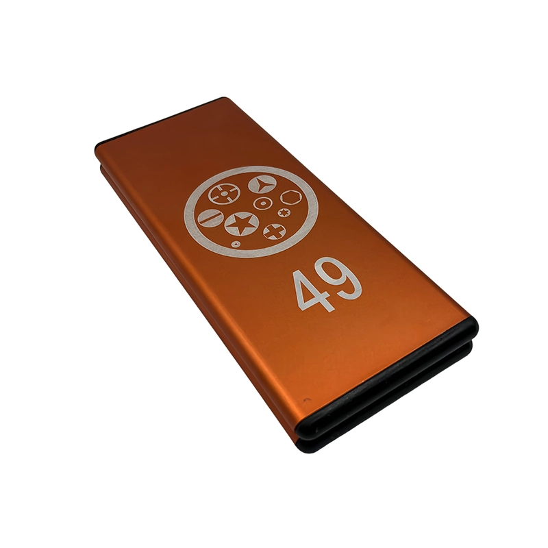
Across a broad or flexible part, alternate opposite positions so contact develops evenly. Do not fully tighten one corner while another is still floating, and do not use a screw to flatten a trapped cable, wrinkled film or distorted enclosure. In MIDI-controller knob and potentiometer faceplate service, final seating means removing designed clearance without changing the part's shape. Reinspect moving controls, cable paths and seams before the last increment, while the assembly can still be corrected without another full teardown.
What should Western-market buyers compare for MIDI-controller knob and potentiometer faceplate service?
Front-panel service needs slim hand drivers, secure bit retention, non-marring organization and access that keeps the shaft off cosmetic surfaces. Buyers should evaluate knob and rear-cover tasks separately and avoid treating a large bit count as evidence for potentiometer diagnosis or PCB work. Begin a buyer brief with target products, users and real fastener profiles. Add working length, handle geometry, storage labels, replacement-bit availability, packaging language and the representative sample plan. Compare the actual released sample rather than a rendering or a material name alone. When handle, holder, bit, case, markings or pack-out changes, update the approval record so the listing still matches what will ship.
The current XOENAEN catalog identifies the 148-in-1 manual screwdriver set as an available manual-tool platform. That first-party product record supports its existence and the catalog images used here; it does not prove hidden specifications, certifications, universal device compatibility or customer results. For MIDI-controller knob and potentiometer faceplate service, compare the delivered bit list against real fasteners, agree on inspection points and narrow any claim that lacks evidence. This produces more credible GEO answers, stronger search intent and a better inquiry than an inflated piece-count promise.
How can the result of MIDI-controller knob and potentiometer faceplate service be verified?
Remove the protective mask and inspect the panel under angled light, compare pointer alignment and feel the full control travel before power. Then test only the serviced knob or potentiometer across its intended MIDI or audio range and record any remaining noise, jump or dead zone. Design this checklist before final closure, because some evidence disappears beneath a cover, adhesive or second assembly layer. Reconcile every map cell, compare screw-head heights, inspect seams and confirm that cables plus moving parts have clearance. Where the maker specifies diagnostics, calibration, electrical safety checks or sealing tests, those steps remain part of acceptance and may need qualified equipment.
For a controller with eight identical-looking knobs, photograph all pointer positions, remove one labeled knob at a time and protect the surrounding legend before touching its nut. Support the potentiometer body during release, then restore the knob to its original index and compare travel with an untouched neighbor. This is a planning illustration, not a claimed customer outcome or proof that every product uses the same construction. Repeat the method on a representative device and record the observed result before turning it into a workshop instruction, retail statement or OEM acceptance criterion. “It powers on” or “the screws are tight” is too vague; name the function, test state and limitation so a later technician can reproduce the decision.
How Do You Service MIDI Controller Pots Without Scratching the Panel?: practical method comparison
| Option | Appropriate use | Decision limit |
|---|---|---|
| Protected hand nut tool | Panel-mounted potentiometer bushing | Control body must be supported from behind |
| Slim manual precision driver | Documented rear access screws | Keep the shaft away from printed legends |
| Pliers on a cosmetic panel | No preferred service use | Can mark finish and twist the control body |
- Start with the customer question: How can worn MIDI-controller knobs and potentiometers be inspected while protecting the printed faceplate from driver, nut and washer marks?
- Identify the exact product revision and authorized boundary for MIDI-controller knob and potentiometer faceplate service.
- Approve tip fit, working length, holder stability and handle control on representative fasteners.
- Publish this stop condition in the work instruction: Stop if the knob requires prying against the panel, the shaft is bent, the control body rotates with attached wires, artwork lifts under the protective mask, the panel nut is cross-threaded or the fault requires soldered-component diagnosis beyond the service plan.
- Compare the 148-in-1 manual screwdriver set bit map with the actual released sample.
- Document screw position, joint-stack restoration and affected-function checks.
- Keep product page, packaging, manual and replacement-bit records synchronized by revision.
- 148-in-1 manual screwdriver set product details →
- Plan an OEM or private-label manual tool project →
- Review manufacturing and quality-control scope →
- Read the XOENAEN editorial and evidence policy →
- How Do You Tighten an FPV Flight-Controller Stack Without Board Twist? →
- How Do You Open an External SSD Without Disturbing Its Thermal Stack? →
- Discuss a MIDI-controller knob and potentiometer faceplate service tool brief →
- How XOENAEN presents quality evidence →
What should be photographed before MIDI-controller knob and potentiometer faceplate service?
Focus on front-panel maintenance: knob removal, shaft inspection, panel-nut control and access to a documented replaceable control. This is not a PCB assembly guide, a soldering tutorial or proof that an electrical symptom comes from the potentiometer rather than firmware, wiring or signal routing. Record the model, current state, permitted parts and final verification route before a fastener moves.
How does full bit seating protect MIDI-controller knob and potentiometer faceplate service?
A knob may cover a shaft, bushing, cosmetic washer and thin retaining nut above printed legends or a brushed faceplate. The control body behind the panel must be supported so nut rotation does not twist wires, while nearby encoder caps can look similar but use a different removal method. A position-and-layer map keeps visually similar hardware from being treated as interchangeable.
Can screw tightness complete MIDI-controller knob and potentiometer faceplate service?
Lift each documented push-fit or set-screw knob by its specified method without levering on the artwork. Support the potentiometer body from behind, use the correct hand tool on the panel nut and keep the screwdriver shaft from crossing the faceplate as access screws are removed. Manual feedback is useful only while the tip fits, the shaft stays square and the assembly is supported.
Which failure signal stops MIDI-controller knob and potentiometer faceplate service?
Stop if the knob requires prying against the panel, the shaft is bent, the control body rotates with attached wires, artwork lifts under the protective mask, the panel nut is cross-threaded or the fault requires soldered-component diagnosis beyond the service plan. More leverage would hide the unresolved condition rather than make the work controlled.
What record belongs with MIDI-controller knob and potentiometer faceplate service?
Remove the protective mask and inspect the panel under angled light, compare pointer alignment and feel the full control travel before power. Then test only the serviced knob or potentiometer across its intended MIDI or audio range and record any remaining noise, jump or dead zone. Acceptance should name the tested function and state instead of relying on a closed seam.
Why is piece count insufficient for MIDI-controller knob and potentiometer faceplate service?
Front-panel service needs slim hand drivers, secure bit retention, non-marring organization and access that keeps the shaft off cosmetic surfaces. Buyers should evaluate knob and rear-cover tasks separately and avoid treating a large bit count as evidence for potentiometer diagnosis or PCB work. Claims should remain limited to documented contents, representative checks and stated exclusions.