For soldering-station controller and connector service, first confirm the exact model, authorized repair scope, safe power state and fastener map. Use a bit that fully fills the recess, support the assembly, preserve every screw position and start reassembly by hand. Stop when alignment or resistance changes, then verify affected functions with the maker’s procedure. Screw tightness alone does not prove a safe or complete repair.
soldering-station controller and connector service manual screwdriver workflow
soldering-station controller and connector service manual screwdriver workflow is a controlled method for defining the service boundary, matching a full-fitting bit, preserving screw and component positions, recognizing a stop condition and verifying the restored assembly without treating extra hand force as a substitute for product-specific instructions.
What work is actually inside soldering-station controller and connector service?
This article separates safe enclosure planning from energized electrical repair. A soldering station can contain mains voltage, hot components and calibrated temperature-control circuits. Internal access is only appropriate for qualified personnel following the maker’s isolation, discharge and verification procedure. Before opening anything, separate the requested outcome from the mechanical step. A failed function can originate in software, a connector, contamination, a worn part or the surrounding assembly, so the presence of screws is not proof that loosening them is the correct diagnosis. Document what the product does now, what changed and which evidence will distinguish a fastening problem from a component problem. That short record protects the device and prevents an accessory list from becoming a substitute for a service plan.
Station hardware spans case screws, grounded connector plates, display boards, strain reliefs and sometimes heat-sink mounts. Similar heads may carry different electrical or mechanical roles. Grounding hardware and insulating washers must stay identified, while driver reach should not place the hand or shaft near live sections. Treat each joint as a stack of parts rather than an isolated screw. The stack may contain a bracket, board, washer, seal, cable, spacer, contact or moving feature, all of which have to return to the same geometry. A manual driver gives useful feedback only when its bit fits, its shaft stays straight and the workpiece is supported. If any of those conditions is missing, the correct response is to improve access or stop, not to squeeze the handle harder.
How should the device be prepared before soldering-station controller and connector service?
Turn the station off, unplug it, allow the iron and enclosure to cool and follow the documented wait or discharge time. Confirm authorization and test equipment, photograph ground points and cable routes, and map case, connector, board and heat-sink screws separately. Establish an ESD-controlled area for low-voltage boards. Preparation is part of the repair, not idle time. It creates the reference that allows another person to understand where each screw, cable and small part belongs. Use photographs that show orientation as well as close details, and add labels where identical hardware crosses assembly boundaries. If a procedure depends on a particular fold angle, switch position or module state, record it before the assembly can move.
For soldering-station controller and connector service, set up the bench around the product’s hazards and the size of its loose parts. A stable padded support prevents the driver hand from also holding the device. Good lighting reveals recess fit and cable edges, while a divided map prevents mixed screw lengths. Apply ESD controls where boards are exposed and keep batteries, mains sections, optical surfaces, seals and energized parts within their own approved handling rules. The tool set should arrive only after this safe work state has been established.
Which bit and handle fit soldering-station controller and connector service best?
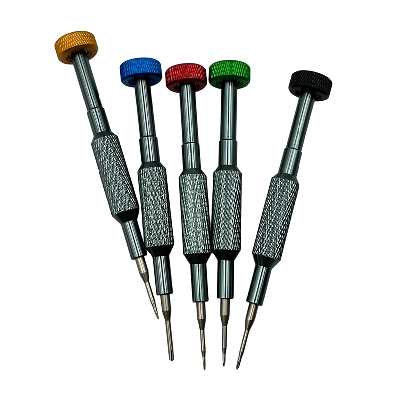
Begin with the fastener in front of you, not a remembered size from a similar product. Clean the recess without damaging it, compare candidate tips under magnification and choose the profile that reaches the full depth with minimal rotational play. Check that the bit shoulder and holder clear nearby surfaces throughout the turn. For soldering-station controller and connector service, a compact rotating cap often improves fingertip control, while a longer shaft is useful only when it remains straight and does not touch the assembly around the recess.
For soldering-station controller and connector service, handle size changes how easily an operator can exceed the needs of a miniature joint. Use the smallest comfortable grip that maintains alignment, and reserve higher leverage for a documented breakaway step on a supported fastener. Magnetism can help retain ferrous screws, but it is neither universal nor always appropriate around sensors, loose metal or sensitive components. A complete selection decision therefore records profile, nominal size, working length, holder play, access angle and the explicit point at which the operator must stop.
What removal and reassembly order controls soldering-station controller and connector service?
Open only after safe-state verification, support the cover and release tethered controls before moving it aside. Keep grounding fasteners and washers in dedicated cells. During rebuild, restore insulation, strain relief and ground joints exactly, start enclosure screws by hand and keep them loose until connectors and panels align naturally. Each movement should answer one question: what has just been released, and what might now be unsupported? Move the removed fastener directly to its map instead of placing it temporarily on the bench. Where a cover spans several positions, loosen progressively so stored load is not concentrated at one corner. Support a bracket, board or module before its last fastener and never pull two halves apart until tethering cables and clips have been identified.
On the way back from soldering-station controller and connector service, restore the non-fastener stack first: locators, contacts, seals, washers, cables, springs and supports. Place the retained part without using screws and check whether it sits naturally. Start every fastener by hand for at least the first engagement, back out immediately if resistance arrives too soon and use an alternating sequence across wide or flexible parts. Final seating means eliminating designed clearance without bowing, crushing or forcing the assembly into a shape it did not have.
Which risks and stop signs matter during soldering-station controller and connector service?
Mains energy, stored charge and residual heat can injure an unqualified repairer. A substituted grounding screw or missing insulating washer may create a hidden safety defect. Driver slips can bridge conductors, and over-tightening a panel connector can crack the board or rotate internal wiring. These are application risks rather than theoretical tool defects, so they should appear in the job instruction and buyer brief. A bit can fit the head yet still be inappropriate because the shaft has no clearance, the screw has another function or the assembly is not supported. Likewise, a cover can close while a hidden cable, washer or contact remains wrong. Avoid broad promises such as “safe for all electronics” because the risk is created by the complete joint and service context.
The controlling stop rule is: Stop when safe isolation cannot be verified, a ground stack is undocumented, insulation is damaged, a hot component remains, or the required electrical safety and temperature-calibration checks are not available. Stop rules must be practical enough that an operator can recognize them before irreversible damage. Photograph the condition, keep the hardware map unchanged and escalate with the model, fastener position and observed resistance. Do not substitute a larger handle, impact, heat, chemical or improvised extractor without a separate approved method. A disciplined stop preserves diagnostic evidence and usually costs less than repairing damage caused by one more turn.
What does a realistic soldering-station controller and connector service example look like?
For a documented front-connector replacement, let the station cool and reach its verified safe state, then photograph the ground and strain-relief stack. Support the connector while removing its screws, restore every washer in order and check cable clearance before closing. Complete qualified safety and temperature verification before production use. This example is a planning illustration, not a customer result or a statement that the named XOENAEN set has been tested on every device described. It shows why screw location, product state and a defined test matter together. A workshop should repeat the method on its own representative assembly and record the observation before adopting it as a standard operating instruction.
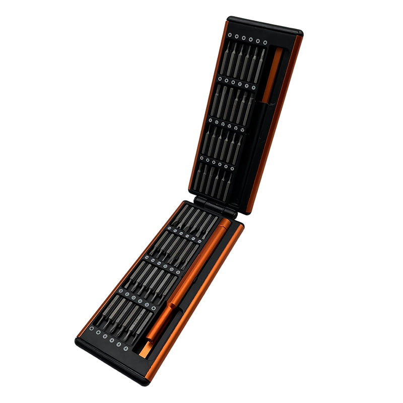
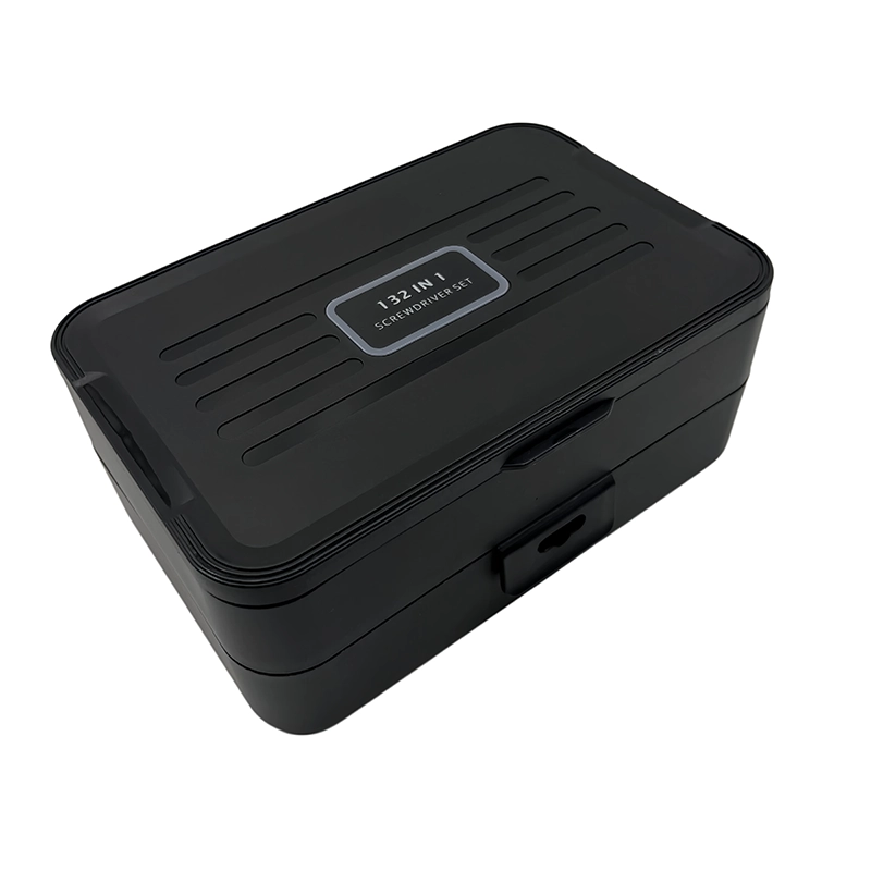
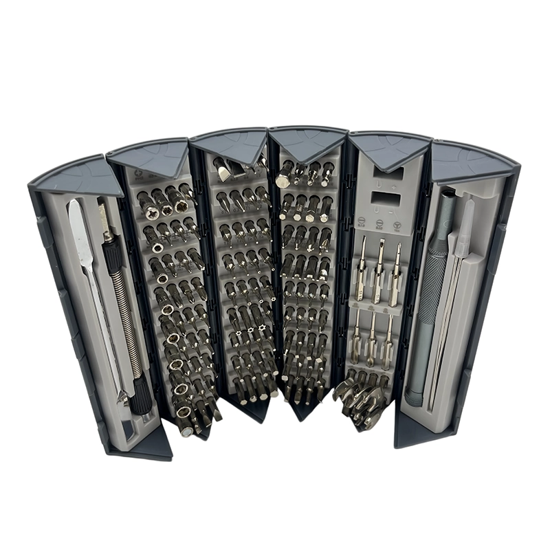
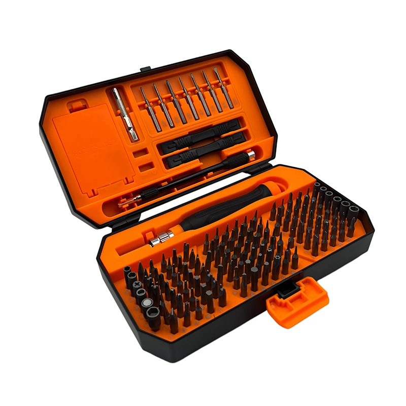
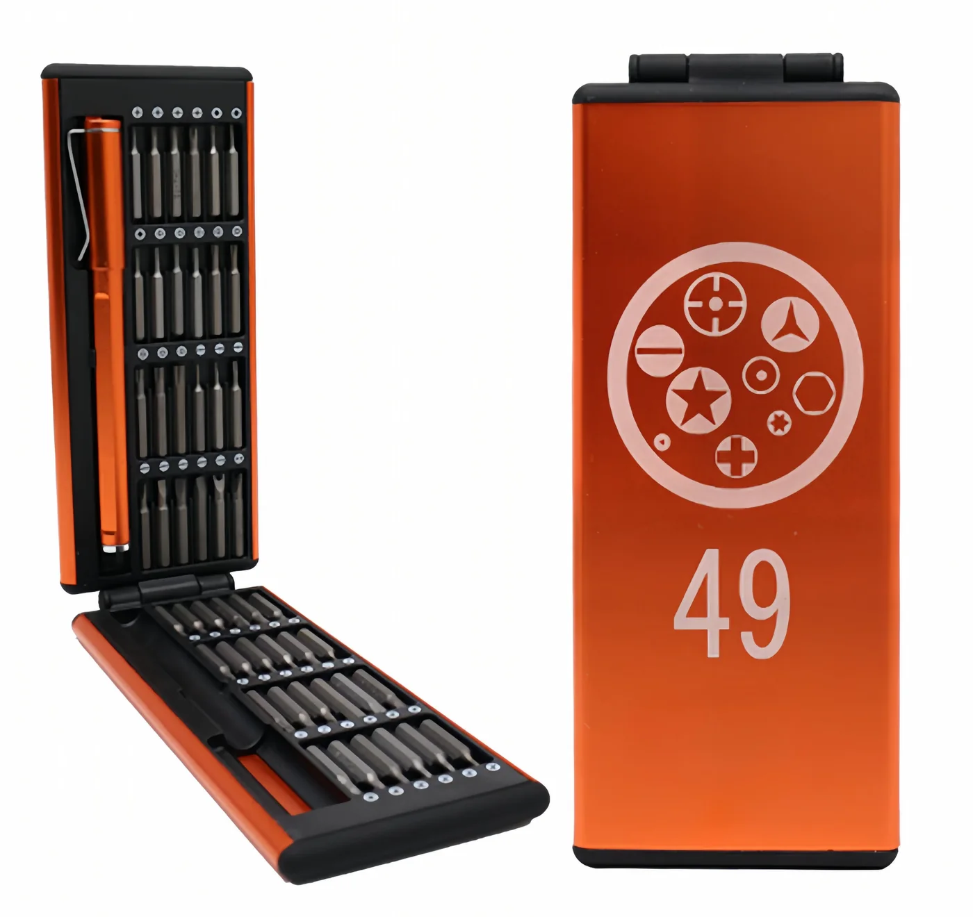
The current XOENAEN catalog identifies the 132-in-1 manual screwdriver set as an available manual-tool platform. That first-party record supports product existence and the referenced catalog images; it does not prove a hidden specification, certification, device-wide compatibility or service-life figure. For soldering-station controller and connector service, compare the actual bit list and sample with the intended fasteners, then agree on acceptance criteria, package claims and replenishment. If the evidence does not cover a claim, narrow the claim rather than filling the gap with confident language.
How can soldering-station controller and connector service be verified after reassembly?
Before power, inspect insulation distances, ground-joint restoration, connector orientation, strain relief and loose hardware. Qualified personnel should complete the maker’s continuity, safety and temperature checks with suitable equipment. Stable heat at one dial setting is not enough to prove calibration across the operating range. Build the checklist before the device is closed, because some observations disappear beneath the final cover or adhesive. At minimum, reconcile the parts map, compare seams and head heights, confirm that moving parts and cables have clearance and inspect disturbed contacts or seals. Where a product maker specifies calibration, software diagnostics, electrical safety checks or ingress testing, those activities remain part of the acceptance process and may require qualified equipment.
Write down what was actually checked, under what state and with which reference. “Works” is not a useful result if only one function or one position was tried. For soldering-station controller and connector service, repeat the customer’s original symptom in a safe, controlled way and add adjacent functions that could have been affected by the teardown. An observation on one representative device supports that repair decision; it does not establish universal durability, certification or compatibility for a complete market.
What should Western-market buyers compare for soldering-station controller and connector service?
A station-service kit needs insulated-work boundaries defined separately from bit selection, plus accurate case and board profiles, longer shafts where specified and dedicated storage for ground hardware. Buyers should demand application limits and replacement-bit control; a screwdriver set should never be marketed as electrical-safety equipment. For European and North American repair, hobby or retail programs, the useful commercial specification starts with target devices, users and fastener profiles. Add working length, material tied to the released SKU, handle geometry, case labeling, replacement-bit availability, packaging languages and the sample method. Ask the supplier to identify assumptions and exclusions so a buyer can distinguish verified contents from application guidance and future options.
For soldering-station controller and connector service, do not rank sets by piece count or a single alloy name. Build a fastener matrix from representative products, measure whether the tip seats fully, observe holder wobble and check whether users can find and return the right bit. Review the exact sample that will support the listing. Any change to tips, holder, handle, case, marking or package needs revision control. Private-label artwork should be approved after the working configuration is frozen, not before the core fit questions have been answered.
Which Manual Screwdriver Is Appropriate for Soldering-Station Service?: method comparison
| Option | Appropriate use | Decision limit |
|---|---|---|
| Manual precision set | De-energized case and board fasteners | Not electrical protective equipment |
| Insulated rated driver | Defined electrical work by qualified staff | Rating and procedure must match hazard |
| Powered driver | Controlled factory enclosure assembly | Poor choice for diagnostic teardown |
- Confirm the real customer question: How should a technician approach enclosure, display and connector screws in a temperature-controlled soldering station?
- Identify the exact device, fastener profiles and authorized boundary for soldering-station controller and connector service.
- Approve tip fit, working length, holder stability and handle control on representative screws.
- Document this application stop rule: Stop when safe isolation cannot be verified, a ground stack is undocumented, insulation is damaged, a hot component remains, or the required electrical safety and temperature-calibration checks are not available.
- Compare the delivered 132-in-1 manual screwdriver set bit map with the released sample.
- Define position mapping, reassembly observations and affected-function checks.
- Keep listing, manual, package and replacement-bit claims synchronized by revision.
- 132-in-1 manual screwdriver set product details →
- Plan a private-label manual screwdriver project →
- Review manufacturing and quality-control scope →
- Read the XOENAEN editorial and evidence policy →
- How Do You Service a Studio Microphone Body Without Touching the Capsule? →
- How Should Audio Mixer Fader-Panel Screws Be Removed and Rebuilt? →
- Continue with the manual-screwdriver-bench-power-supply-enclosure-boundary topic →
- How XOENAEN presents quality evidence →
How should a technician define the scope of soldering-station controller and connector service?
This article separates safe enclosure planning from energized electrical repair. A soldering station can contain mains voltage, hot components and calibrated temperature-control circuits. Internal access is only appropriate for qualified personnel following the maker’s isolation, discharge and verification procedure. The model, safe state, authorized components and final verification route should be recorded before a bit is selected or a cover is moved.
Where should removed hardware go during soldering-station controller and connector service?
Station hardware spans case screws, grounded connector plates, display boards, strain reliefs and sometimes heat-sink mounts. Similar heads may carry different electrical or mechanical roles. Grounding hardware and insulating washers must stay identified, while driver reach should not place the hand or shaft near live sections. A position record prevents the head shape from being mistaken for proof that two fasteners have the same length or function.
Can screw tightness prove soldering-station controller and connector service is complete?
Open only after safe-state verification, support the cover and release tethered controls before moving it aside. Keep grounding fasteners and washers in dedicated cells. During rebuild, restore insulation, strain relief and ground joints exactly, start enclosure screws by hand and keep them loose until connectors and panels align naturally. Hand control is preferred where resistance, fragile supports or mixed hardware require the operator to feel a change and stop before damage.
Which failure signal calls for escalation in soldering-station controller and connector service?
Stop when safe isolation cannot be verified, a ground stack is undocumented, insulation is damaged, a hot component remains, or the required electrical safety and temperature-calibration checks are not available. That condition means the present method, evidence or equipment is insufficient; more leverage would only hide the unresolved cause.
How can a second technician review soldering-station controller and connector service?
Before power, inspect insulation distances, ground-joint restoration, connector orientation, strain relief and loose hardware. Qualified personnel should complete the maker’s continuity, safety and temperature checks with suitable equipment. Stable heat at one dial setting is not enough to prove calibration across the operating range. Completion must be tied to the affected functions and safety controls, rather than to a closed seam or an installed screw alone.
What should an OEM brief say about tools for soldering-station controller and connector service?
A station-service kit needs insulated-work boundaries defined separately from bit selection, plus accurate case and board profiles, longer shafts where specified and dedicated storage for ground hardware. Buyers should demand application limits and replacement-bit control; a screwdriver set should never be marketed as electrical-safety equipment. The supplier’s claim should remain limited to documented product contents and representative application checks, with assumptions and exclusions stated plainly.