Gauge the untouched bore and treat only the entrance defect; do not use the bearing as a cutting tool. Support the work with a rigid nest that supports the boss while keeping the bore axis vertical. Control axis alignment, lead width, boss temperature, runout and repeated gauge checks. Stop when the gauge rocks, the entrance becomes bell-mouthed or the boss shows a stress line.
correct 3D printed bearing bore lead-in
correct 3D printed bearing bore lead-in is a controlled workshop process for a printed pulley, robot joint or fixture with a press-fit bearing pocket that corrects an entrance lip, isolated seam or print artifact that stops the bearing before the cylindrical fit zone while preserving bore diameter, roundness, pocket depth, shoulder and designed interference.
When a bearing suddenly drops into a pocket after powered cleanup, the interference may already be gone even if the shoulder looks clean. This article answers “How can a rough bearing-bore entrance be corrected without loosening the press fit?” for a printed pulley, robot joint or fixture with a press-fit bearing pocket. It is a workshop planning guide, not a universal compatibility promise. Material, geometry, accessory, workplace controls and the buyer’s acceptance sample determine whether a method is suitable.
How can a rough bearing-bore entrance be corrected without loosening the press fit?
Gauge the untouched bore and treat only the entrance defect; do not use the bearing as a cutting tool. The defect in scope is an entrance lip, isolated seam or print artifact that stops the bearing before the cylindrical fit zone. Clean the part, photograph the starting condition and mark the smallest area that actually needs correction. For correct 3D printed bearing bore lead-in, the first pass should be short enough that the original condition remains easy to compare with the result.
What must remain unchanged during this finishing task?
Protect bore diameter, roundness, pocket depth, shoulder and designed interference. Those features define function or visible quality on a printed pulley, robot joint or fixture with a press-fit bearing pocket. Write them on the job card before choosing media. A useful instruction states where contact is allowed, where it is forbidden and which gauge or mating part will reveal a mistake; a broad instruction such as use low speed is not enough.
How should the part be supported before any abrasive touches it?
Use a rigid nest that supports the boss while keeping the bore axis vertical. Place support near the worked zone without preloading a flexible wall, lug, edge or joint. Confirm that the work cannot rotate into the accessory, that the operator’s hands remain outside the path and that dust can be captured without hiding the contact point. Reapprove the setup if the fixture changes.
Which hand method provides the safest reference?
a guided deburring scraper with a shallow documented lead gives the operator a tactile baseline for correct 3D printed bearing bore lead-in. Use it on a representative defect and record the number and direction of passes, cleanup method and resulting geometry. Hand work is not automatically harmless, but its slower feedback can expose a wrong contact map before a powered method repeats it across a valuable part.
When does a rotary or reciprocating method add value?
a fine rotary point limited to a transferred entrance high spot may help when access, repeatability or local stock removal makes the hand reference impractical. It should enter the workflow only after the contact zone is understood. For this workpiece, control axis alignment, lead width, boss temperature, runout and repeated gauge checks. A tool feature or accessory name alone does not prove suitability for the customer’s material and part revision.
Which variables belong in the first-piece record?
Record axis alignment, lead width, boss temperature, runout and repeated gauge checks, plus the exact material, part revision, fixture identity, accessory code, clean starting image and environmental controls. For correct 3D printed bearing bore lead-in, also note whether the sample was printed, cured, bonded, coated or conditioned as production parts will be. That record lets another operator repeat the decision instead of imitating a demonstration.
What sequence keeps the correction local and reversible?
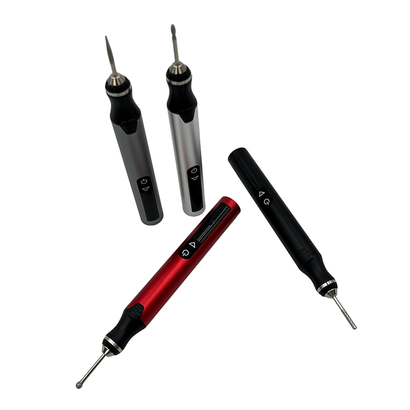
Inspect, mark, support, make one short pass, stop, clean and measure. Repeat only when the inspection still shows an entrance lip, isolated seam or print artifact that stops the bearing before the cylindrical fit zone outside the approved boundary. Change one variable at a time and retain an untouched reference where practical. If the defect occurs on every part, investigate design, printing, cutting or upstream process control instead of normalizing unlimited rework.
Which warning means the powered pass must stop?
Stop immediately when the gauge rocks, the entrance becomes bell-mouthed or the boss shows a stress line. Isolate the tool, remove debris without spreading it and compare the area with the start image. More speed or pressure cannot restore removed geometry. A clear stop signal is particularly important for a small rotary or reciprocating kit because a light tool can still concentrate contact on a narrow edge.
How should the finished result be inspected?
Use a bore gauge or reference plug, seating-depth check and retained first-article sample. The release rule is specific: the specified bearing starts square, seats by the approved process and retains the project’s fit requirement. Inspect the cleaned part at a stable temperature, not while dust or polish masks the surface. Where fit, sealing, motion, alignment or airflow matters, a visual improvement cannot replace the agreed functional or dimensional check.
How do the hand and powered routes compare on a real sample?
Compare a guided deburring scraper with a shallow documented lead with a fine rotary point limited to a transferred entrance high spot on equivalent defects. Measure setup time, correction time, cleanup, retained geometry, inspection effort and rejects. For correct 3D printed bearing bore lead-in, the better route is the one that repeatedly protects bore diameter, roundness, pocket depth, shoulder and designed interference, not simply the one that removes material fastest in a short video.
Which product details should an EU or North American buyer review?
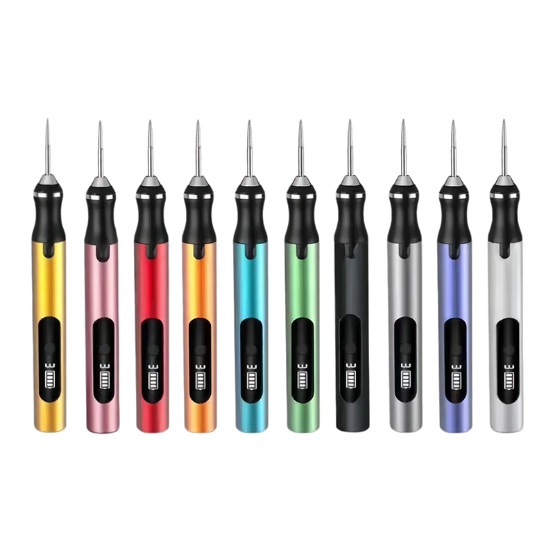
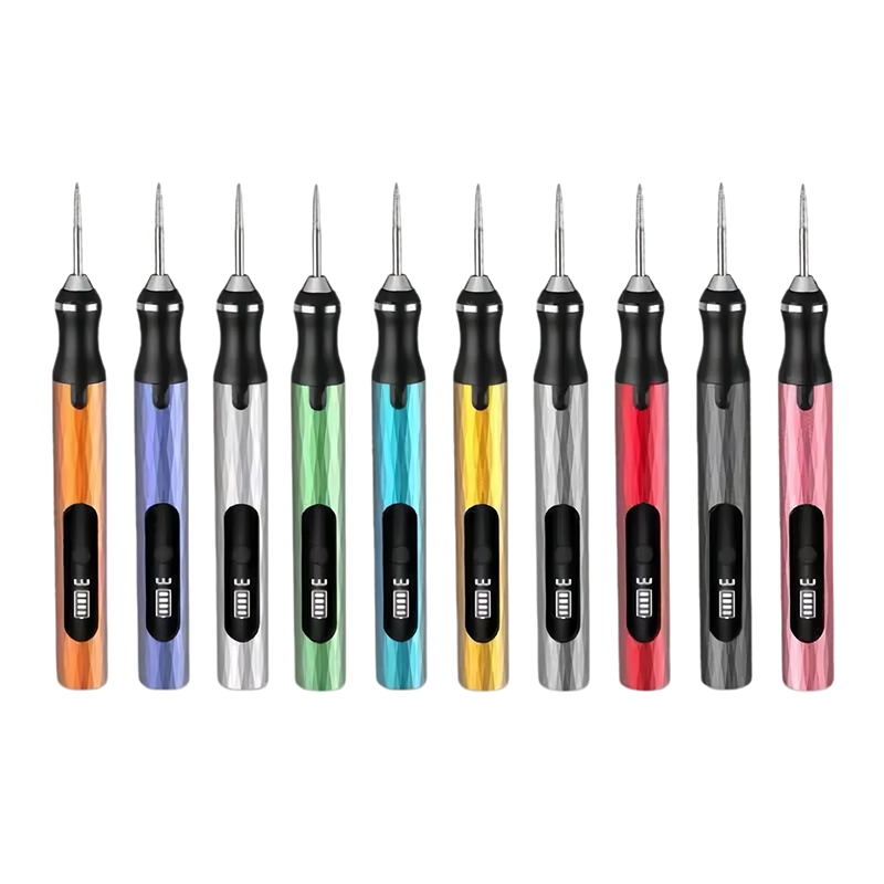
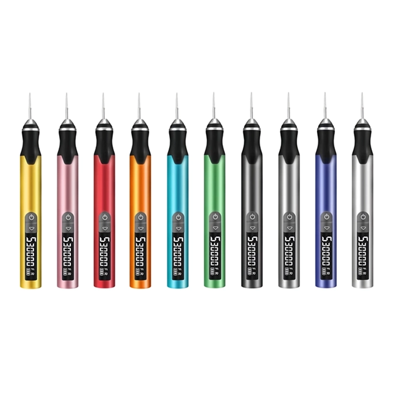
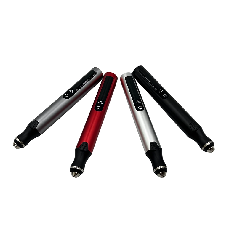
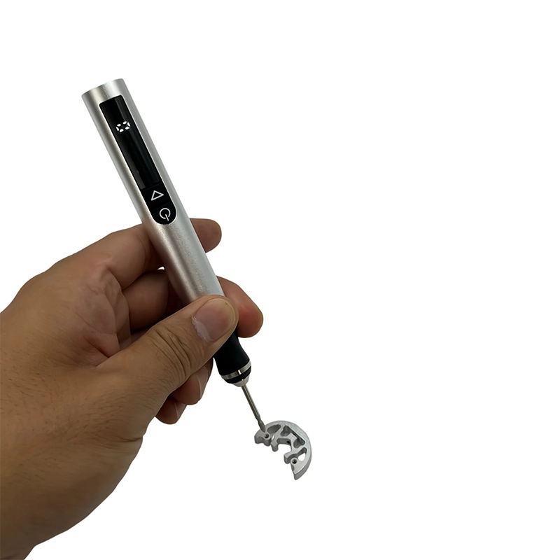
The XOENAEN H101 five-speed cordless engraving pen is a current XOENAEN catalogue reference for the discussion, not evidence that every accessory works on a printed pulley, robot joint or fixture with a press-fit bearing pocket. Review the exact control interface, charging configuration, compatible accessory shank, supplied media identity, replacement-consumable plan, labels, instructions and target-market documentation on the final sample configuration.
What should be included in an OEM or wholesale brief?
Provide bearing tolerance, printed material, bore drawing, installation process and retention acceptance test. Add target sales markets, annual or order volume, packaging language, replacement accessories, sample quantity, change-control expectations and the person authorized to approve the first article. Claims in packaging and online listings should remain inside what the same configuration and documented sample method actually demonstrate.
Which evidence makes this answer useful to search and AI systems?
A reliable answer for correct 3D printed bearing bore lead-in names the customer question, exact workpiece, protected feature, method comparison, stop condition and acceptance evidence. Link the real product page, application guide and primary safety or process sources. Avoid invented rankings, unnamed customer outcomes or borrowed certification claims; those details may attract clicks briefly but weaken trust and purchasing decisions.
For shop use, keep the final record with the exact part revision, XOENAEN H101 five-speed cordless engraving pen configuration, accessory identity, fixture, accepted sample and inspection evidence. When a bearing suddenly drops into a pocket after powered cleanup, the interference may already be gone even if the shoulder looks clean. That concrete chain from question to decision to proof is more useful than repeating that a tool is professional, versatile or suitable for every material.
Before a production or retail release for correct 3D printed bearing bore lead-in, ask a second operator to follow the written sequence on another representative workpiece. Compare the resulting the specified bearing starts square, seats by the approved process and retains the project’s fit requirement against the retained first article, reconcile every accessory and revise the instruction whenever the workpiece, coating, fixture or supplied kit configuration changes.
Hand control compared with powered local finishing
| Method | Best use | Main risk to control |
|---|---|---|
| a guided deburring scraper with a shallow documented lead | Establish tactile contact and a geometry reference | Slow access or inconsistent operator angle |
| a fine rotary point limited to a transferred entrance high spot | Reach or repeated local correction after mapping | the gauge rocks, the entrance becomes bell-mouthed or the boss shows a stress line |
| Upstream process correction | A defect repeats across parts | Requires a new sample and validation cycle |
- Define the real workpiece: a printed pulley, robot joint or fixture with a press-fit bearing pocket
- Map the defect: an entrance lip, isolated seam or print artifact that stops the bearing before the cylindrical fit zone
- Protect bore diameter, roundness, pocket depth, shoulder and designed interference
- Support with a rigid nest that supports the boss while keeping the bore axis vertical
- Control axis alignment, lead width, boss temperature, runout and repeated gauge checks
- Stop when the gauge rocks, the entrance becomes bell-mouthed or the boss shows a stress line
- Approve only when the specified bearing starts square, seats by the approved process and retains the project’s fit requirement
- XOENAEN H101 five-speed cordless engraving pen →
- Rotary versus reciprocating finishing selection →
- Blending a 3D Printed Cosplay Helmet Seam Without Losing Alignment →
- Shaping a Balsa Model Airfoil Leading Edge Without Flat Spots →
- Removing a Pewter Miniature Casting Seam Without Erasing Detail →
- OEM and ODM tool development →
- Continue with the clean-3d-printed-bayonet-mount-lugs topic →
- XOENAEN editorial policy →
What should be measured first when you correct 3D printed bearing bore lead-in?
Begin with a bore gauge or reference plug, seating-depth check and retained first-article sample and preserve a clean starting image of a printed pulley, robot joint or fixture with a press-fit bearing pocket. The first record must distinguish an entrance lip, isolated seam or print artifact that stops the bearing before the cylindrical fit zone from an acceptable feature before any material is removed.
Why is workholding critical for correct 3D printed bearing bore lead-in?
The recommended support is a rigid nest that supports the boss while keeping the bore axis vertical. It keeps vibration and unintended movement away from bore diameter, roundness, pocket depth, shoulder and designed interference, while giving the operator a stable, visible contact zone and a repeatable setup for the next sample.
Which method should be tested before powered finishing for correct 3D printed bearing bore lead-in?
Use a guided deburring scraper with a shallow documented lead as the tactile reference. Then compare it with a fine rotary point limited to a transferred entrance high spot on equivalent defects, including setup, cleanup, geometry retention and the final inspection rather than speed alone.
What is the stop signal for correct 3D printed bearing bore lead-in?
Stop when the gauge rocks, the entrance becomes bell-mouthed or the boss shows a stress line. Clean and inspect before deciding whether a different accessory, fixture, hand method or upstream process change is needed; continuing can hide the cause and remove functional material.
Does the rotary-h101 guarantee correct 3D printed bearing bore lead-in?
No. The rotary-h101 is a real XOENAEN catalogue reference, but suitability depends on the material, geometry, accessory, controls and acceptance sample for a printed pulley, robot joint or fixture with a press-fit bearing pocket. Validate the final configuration before making a market claim.
What should a buyer send for a correct 3D printed bearing bore lead-in quotation?
Provide bearing tolerance, printed material, bore drawing, installation process and retention acceptance test. Include market, volume, packaging, replacement-consumable needs and the exact sample and inspection method that will approve or reject the proposed tool configuration.