Choose hand sanding for broad, sensitive or edge-critical surfaces; use a compact rotary tool for small recesses, holes and curved local defects; consider a reciprocating tool when directional abrasion improves control on a narrow plane. Qualify the material, accessory and acceptance condition on a representative printed coupon before standardizing the process.
3D print finishing tools
3D print finishing tools are manual or powered tools used after printing to remove support remnants, correct local interference, refine visible surfaces, prepare a repair area or prepare a part for paint, bonding or assembly. They should be selected by the feature being corrected, the printed material, the protected dimensions and the approved inspection method.
A good 3D print finishing workflow removes only the material that prevents the next step. That next step may be painting, bonding, assembly, inspection, photography, prototype testing or retail presentation. The tool choice therefore starts with the feature being corrected, the material and the dimension that must be protected—not with the biggest accessory pack or the highest speed printed on a product box.
Rotary, reciprocating and hand-sanding methods are complementary. A compact rotary pen can reach a recessed support scar, a small slot or a curved inner surface. A reciprocating abrasive can provide a more directional stroke on a narrow accessible plane. Hand abrasive is often the easiest way to feel a high spot, keep a datum surface safe and stop exactly at an edge. The strongest process assigns each tool a limited, inspectable job.
This guide is written for makers, workshop buyers and B2B teams choosing a repeatable finishing approach or specifying an OEM 3D print finishing kit. It does not prescribe an RPM, grit sequence, adhesive or safety practice for every polymer. The material supplier's instructions, accessory speed limit, safety data and the approved sample remain the controlling references for a specific job.
What should a 3D print finishing tool protect?
Before choosing an abrasive or powered tool, separate the part into cosmetic and functional zones. Cosmetic zones include visible faces, logos, display surfaces and paint-ready areas. Functional zones include holes, bores, threads, snap fits, sealing faces, locating bosses, bearing seats and surfaces that contact another part. A support scar in a cosmetic zone may need blending; the same scar beside a locating feature may need only the smallest local correction or a reprint.
A practical work card marks three things: where material may be removed, the maximum area that may be touched, and the inspection method after each pass. A part can look smoother yet become unusable if a sharp edge is rounded, a hole is enlarged, a wall is heated or a mating face is no longer planar. Finish quality must be judged against its downstream purpose, not against gloss alone.
For FDM parts, look for seam ridges, support nubs, elephant-foot interference, layer texture and material dragged by heat. For cured resin parts, follow the applicable wash, dry and cure sequence before mechanical finishing, then identify support marks, thin details and surfaces that will be coated or bonded. Formlabs' published guidance is a useful example of a documented post-processing sequence, but resin systems and approved procedures vary by manufacturer and application.
When is hand sanding the best first choice?
Hand sanding is usually the best starting method for a broad accessible face, a sharp boundary, a thin feature or any surface where the operator needs immediate tactile feedback. It is comparatively slow, and that is often its advantage. A small sanding block helps preserve a plane; a flexible abrasive can follow a controlled curve; a folded strip can approach a corner without the momentum of a powered accessory.
Start by measuring or gauging the functional feature, then mark the high area. Work the local defect before blending the surrounding surface. Do not jump to a finer abrasive simply because the part looks less rough. Move on only when the earlier scratch pattern or local high spot is controlled. Clean between steps, inspect under raking light and recheck the actual mating part instead of relying on a visual estimate.
Hand sanding is also the safer comparison baseline for an OEM sample. If a powered configuration cannot improve access, repeatability or operator time over a hand method without damaging the part, it does not justify inclusion in the kit. That test prevents a product brief from becoming a list of accessories with no assigned use case.
When does a rotary tool improve 3D print finishing?
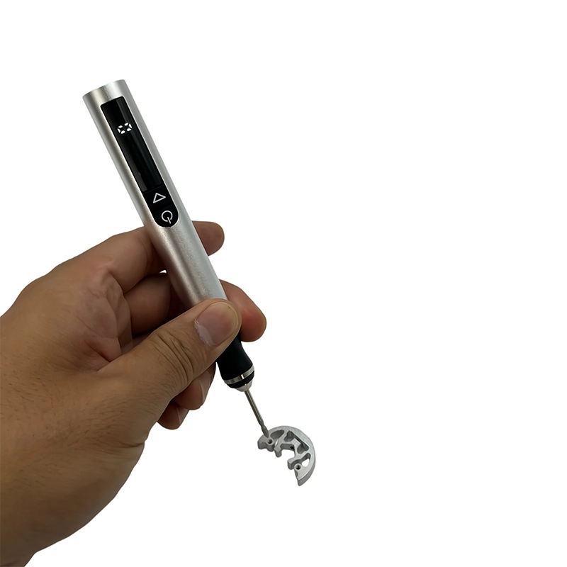
A rotary tool earns its place when the defect is local and access is the real problem: the bottom of a narrow recess, a small internal burr, a hole entrance, a curved support contact, a seam inside a shell or a polishing point that cannot be reached with a flat abrasive. It can cut, grind, drill, blend or polish depending on the approved accessory. It is not automatically the fastest method for every visible face.
The main control variables are accessory geometry, accessory condition, rotational speed, contact time, pressure, support behind the feature and how often the operator stops to inspect. A large accessory has more surface speed than a small point at the same RPM. Staying on one point can build heat or load the abrasive. Pushing harder can remove material less predictably. A smaller practical accessory, a moving contact point and short inspection intervals normally offer more control than forcing a broad wheel into a tight area.
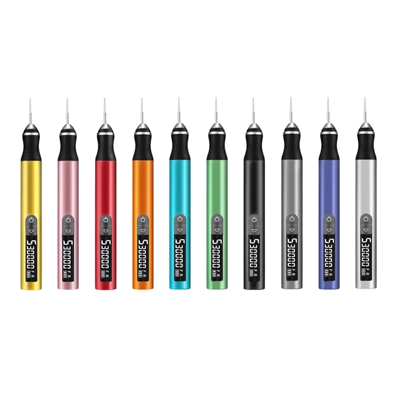
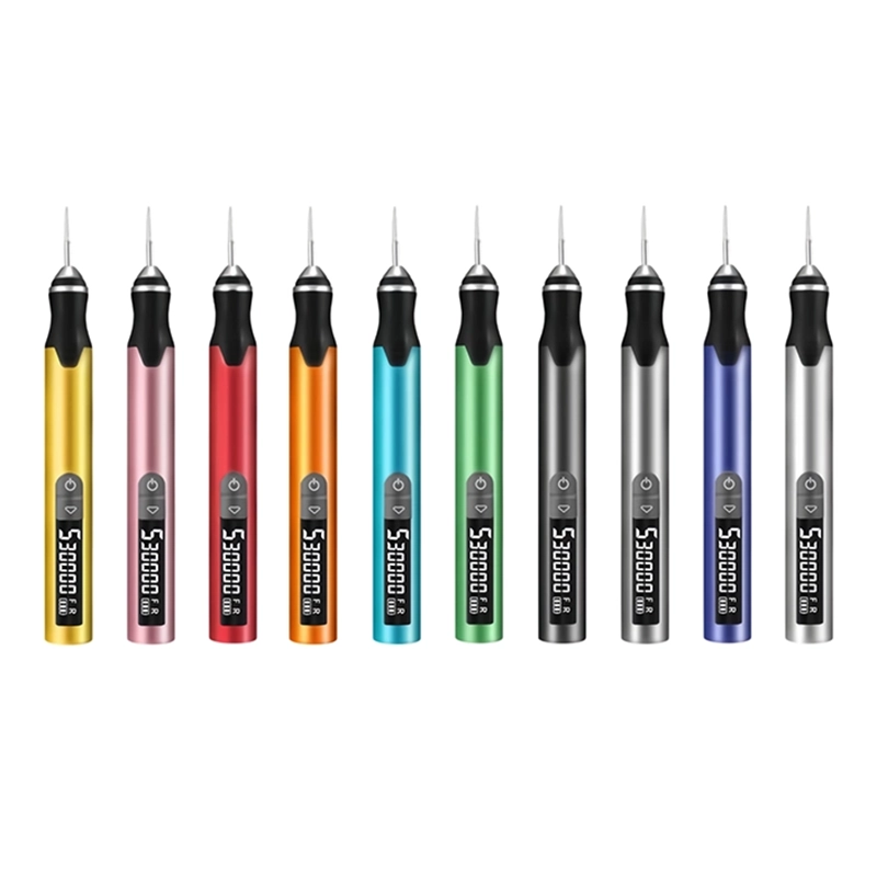
Current XOENAEN product records list D-102, 104 and 106 as three-speed rotary platforms up to 18,000 RPM, while H101 and H102 are five-speed platforms up to 30,000 RPM. The listed accessory interface is a 2.35 mm metal chuck. These are platform specifications, not a claimed setting for PLA, PETG, ABS, nylon, TPU or cured resin. A customer should qualify the permitted accessory and operating point on a coupon printed from the actual material and geometry.
A rotary pen should never be positioned as a replacement for controlled machining where concentricity, flatness, a safety-critical load path or tight dimensional tolerance is required. For example, it may clean a small local ridge at a printed hole entrance, but it should not be used freehand to promise a precision bore. State the acceptance condition first: the measured size, actual fit, edge condition, surface requirement or downstream assembly result.
When is a reciprocating tool the better option?
A reciprocating tool uses a short back-and-forth stroke rather than continuous rotation. That motion can help an operator keep abrasion directional on a narrow accessible plane, blend along a straight boundary or approach a local transition without making a circular contact pattern. It can be valuable when the job is primarily controlled sanding rather than drilling, local grinding or polishing.
It also has limits. Stroke direction can mark a surface if the abrasive is too coarse, vibration can reach a thin wall, and a tool that is held at one edge can still round a corner. The right choice depends on the workholding, the abrasive head, the part stiffness and whether there is a safe run-out area beyond the intended finish zone. A reciprocating method should be trialed on representative coupons, not assumed to protect edges by itself.
XOENAEN's current supplied product records for this site document rotary pen platforms, not an equivalent reciprocating platform. This guide therefore compares motion types as a process decision and does not imply that a rotary product delivers reciprocating performance. For a buyer, that distinction matters: ask for the actual operating motion, stroke or speed range, accessory interface, sample process and acceptance evidence for the proposed tool.
How should an OEM buyer choose a 3D print finishing kit?
Build the specification from jobs, not names. List the printed materials, typical part size, defect types, expected operator skill, shift pattern and final use. Then write a task map: trim support material, flatten a seam, clean a slot, refine a cosmetic face, prepare a bonding area, polish a small detail or repair a non-critical prototype. Each task should name the allowed tool, accessory shape, permitted working area and acceptance check.
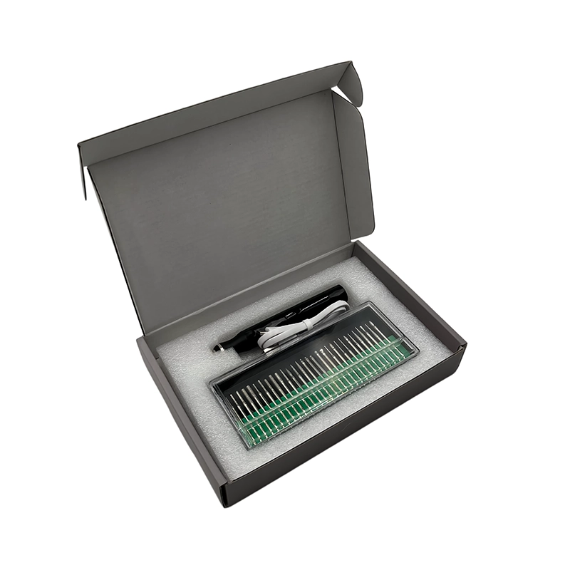
Specify the rotary platform separately from the accessory kit. Record speed positions or range, chuck size, battery and charging arrangement, intended duty pattern, housing control placement, included accessories, spare accessory policy and retail pack-out. For accessories, identify the job, shank diameter, shape, material, intended printed-material family and manufacturer-approved maximum speed. The phrase '30-piece kit' is not an engineering specification.
Send a supplier representative coupon set rather than relying on generic photos. It should include a curved support scar, a narrow slot, a small hole, a cosmetic face, a thin-wall feature, an edge that must stay crisp and one real mating condition. Record starting dimensions, required finish, permitted removal area, test duration and the inspection method. A clear sample plan exposes whether the proposed kit can perform the required work without turning a local correction into a larger defect.
For private-label work, agree the product platform before logo color, packaging graphics and manual translations. Once the platform is confirmed, the project can define brand treatment, product color, bit map, accessory tray, charging cable, warning information, regional packaging, label languages and required documentation. Use the approved sample as the reference for all later copy and imagery; do not make a catalogue rendering the only source of truth.
How do you validate a finishing process before release?
Use the same material, print orientation, wall thickness and important geometry as the production part whenever possible. Test one variable at a time: accessory type, tool motion, speed setting, pressure guidance or time. Photograph and measure the coupon before and after processing. Check cosmetic uniformity under repeatable lighting, then verify the relevant functional condition with the real mating component, a gauge or an agreed measurement method.
Write down failure observations as well as successful settings. Examples include a melted edge, smear, whitening, chipped corner, loaded abrasive, vibration mark, changed hole fit or incomplete support removal. Those observations show where the process boundary is. A robust release instruction says what the operator must avoid, where to stop and how to escalate an unusual part; it does not simply say 'sand until smooth.'
For resin workflows, external technical guidance commonly places washing, drying and any required post-cure before later finishing steps, but the exact order and controls must follow the resin maker's documentation. For all materials, use the accessory manufacturer's permitted speed and the site's required dust, ventilation and personal-protective-equipment controls. The article sources below are included for process context, not as a substitute for a material-specific safety review.
Which tool sequence suits repair and rework?
Repair starts with a decision: is the part cosmetic or lightly loaded enough to rework, or does the damage show a reason to reprint? Reprint if the crack, dimensional error or surface defect affects safety, critical load, a sealed interface, material traceability or an uninspectable joint. A polished repair can hide a problem without restoring the required function.
When repair is appropriate, protect the surrounding geometry first. Remove only loose material, prepare the smallest workable area, follow the adhesive or material maker's instructions, then check alignment and function before cosmetic refinement. A rotary pen can be useful for cleaning a small groove or blending a local high point, while hand abrasive gives better feedback at the final boundary. Treat polishing as the last cosmetic step, never as proof that the repair is structurally acceptable.
Make the purchase decision with a buyer checklist
Use the checklist and comparison below as a starting point for a supplier discussion. It is deliberately specific about the evidence needed and deliberately cautious about performance claims. Any target cycle time, surface result, bit life or dimensional outcome should come from the customer's own representative sample trial, not from a generic article.
A finishing kit is useful only when it reduces a defined problem with a controlled process. The right blend is often simple: hand abrasive for broad and critical boundaries; a compact rotary pen for local access, holes and curves; and a reciprocating approach only when its directional motion demonstrably improves the particular plane or edge. Choose by the part, document the sample and keep the inspection condition visible at every stage.
3D print finishing method comparison
| Method | Best for | Main control risk | How to validate |
|---|---|---|---|
| Hand sanding | Broad accessible faces, crisp boundaries and final blending | Rounding edges or changing a flat surface | Use a block or controlled abrasive; recheck the actual fit and edge |
| Rotary pen | Recesses, holes, curves and small local defects | Heat, oversize features or an aggressive contact point | Test the exact accessory and setting on a representative coupon |
| Reciprocating abrasive | Directional work on a narrow accessible plane | Stroke marks, vibration and edge roll-over | Compare direction, surface and dimensions against a hand-sanded control |
- Define each finishing job, printed material, geometry and protected dimension before choosing a tool.
- Approve the exact accessory map, shank interface and permitted accessory speed rather than an accessory count.
- Use representative coupons with support scars, holes, thin walls, curves and real mating features for supplier samples.
- Record tool motion, setting, inspection method and stop criteria for every approved task.
- Separate functional acceptance from cosmetic appearance and reprint parts with safety- or load-critical damage.
- Confirm packaging, labels, manual language, charging accessories and compliance needs after the platform is approved.
- View the referenced XOENAEN rotary-102 product →
- Select rotary accessories for 3D print post-processing →
- Remove support marks without sacrificing detail →
- Protect edges and fit while sanding 3D prints →
- Plan an OEM or ODM tool project →
- Continue with the 3d-print-sanding-grit-sequence-tool-guide topic →
- How XOENAEN presents quality evidence →
- Related guide: How to polish resin 3D prints after sanding →
What is the best tool for removing support marks from a 3D print?
Use the least aggressive method that reaches the mark. Hand abrasive is often best for an accessible face; a small rotary accessory can help in a recess. Leave a small nub when cutting, then level it gradually so the surface is not gouged.
Can a rotary tool damage PLA, PETG, ABS or resin prints?
Yes. Heat, pressure, a large accessory or staying in one place can smear, chip, load an abrasive or change a dimension. Start on a representative coupon, use the approved accessory setting and inspect after short passes.
When should I choose hand sanding instead of a rotary pen?
Choose hand sanding when you need tactile feedback, a broad flat surface, a sharp boundary or a very small amount of controlled removal. A rotary pen is more useful when the access problem is inside a hole, recess or curved local feature.
Is a reciprocating tool better than a rotary tool for 3D print sanding?
Neither is universally better. A reciprocating motion can be useful for directional work on a narrow plane, while rotation offers access to curves, holes and local point work. Compare both methods on the actual material and geometry with the same acceptance check.
What should an OEM buyer specify in a 3D print finishing tool kit?
Specify the jobs, materials, platform, accessory map, shank interface, settings or speed range, sample coupon, inspection method, packaging and target market. Avoid using only piece count or a generic product image as the requirement.
How do I keep 3D printed holes and mating surfaces accurate during finishing?
Measure or gauge the feature before starting, mark the true interference and remove material only from that area. Clean and test with the real mating component after each short pass. Stop at the required fit, not when the tool seems to move freely.