Choose the finest abrasive that can still remove the real defect, then move to finer stages only after the previous scratch pattern is controlled. Use hand sanding for broad or edge-critical surfaces, a compact rotary tool for local access, and a representative coupon to qualify heat, pressure, speed, fit and final appearance.
3D print sanding grit sequence
A 3D print sanding grit sequence is an ordered set of abrasive stages used to remove support marks, layer texture or repair material while progressively reducing scratches and protecting the part’s edges, holes, mating surfaces and required dimensions.
The best sanding sequence for a 3D printed part is the shortest sequence that removes the defect and preserves the features that matter. A cosmetic display model may need a uniform paint-ready surface. An assembly part may need a clean hole, a crisp locating edge or a controlled bonding face. Those are different finishing jobs, so the grit, tool and stopping point should be different too.
Start by identifying the printed material, the surface requirement and the protected dimensions. PLA, PETG, ABS, nylon, TPU and cured resin respond differently to heat, pressure and abrasive loading. Use the material supplier’s safety and processing instructions, and qualify a new process on a coupon from the same print conditions before applying it to a final part.
What grit should you use first on a 3D print?
Use the finest abrasive that can still remove the actual high spot within a reasonable number of light passes. A coarse abrasive levels support nubs, seam ridges and obvious steps faster, but it also removes more material and leaves a deeper scratch pattern. A fine abrasive is gentler, but it can polish over a high spot without truly leveling it. The correct first grit is therefore determined by the defect height, wall thickness and tolerance—not by a universal number.
For a broad FDM layer texture on a non-critical cosmetic face, a buyer may trial a medium starting grit and then move through finer stages. For a support mark beside a hole or snap fit, begin with a small local abrasive or hand tool and protect the functional feature. For cured resin, complete the applicable wash, dry and post-cure sequence before mechanical finishing. Formlabs documents these stages for its applicable SLA workflow, while the resin maker’s instructions remain the controlling reference.
How should you move from coarse to fine sanding?
Each sanding stage should remove the visible pattern from the previous stage without erasing the geometry. Sand in a consistent direction at the first stage, clean the part, inspect under angled light and continue only when the scratch pattern is reasonably uniform. Change direction at the next stage if that makes the earlier scratches easier to identify. Stop when the acceptance condition is met; a finer grit is not automatically an improvement if it changes an edge or a mating surface.
Use a sanding block for a plane that must stay flat, a flexible abrasive for a controlled curve and a narrow strip only where access requires it. Fingers alone can create a soft hollow in a broad face because pressure concentrates around the contact point. Protect holes, threads, seals, snap hooks, locating bosses and printed lettering with masking or a no-sand boundary on the work card.
Clean between stages. Loose abrasive and print dust can create random scratches that look like a bad grit choice. A repeatable process records the material, print orientation, starting condition, grit or abrasive type, number of passes, inspection lighting and final measurement. This record is more useful for an OEM buyer than a promise that a part will simply be ‘smooth.’
When should a rotary tool replace hand sanding?
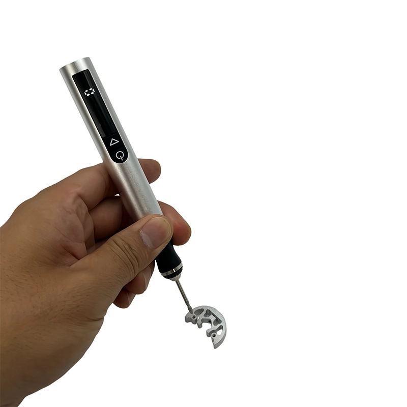
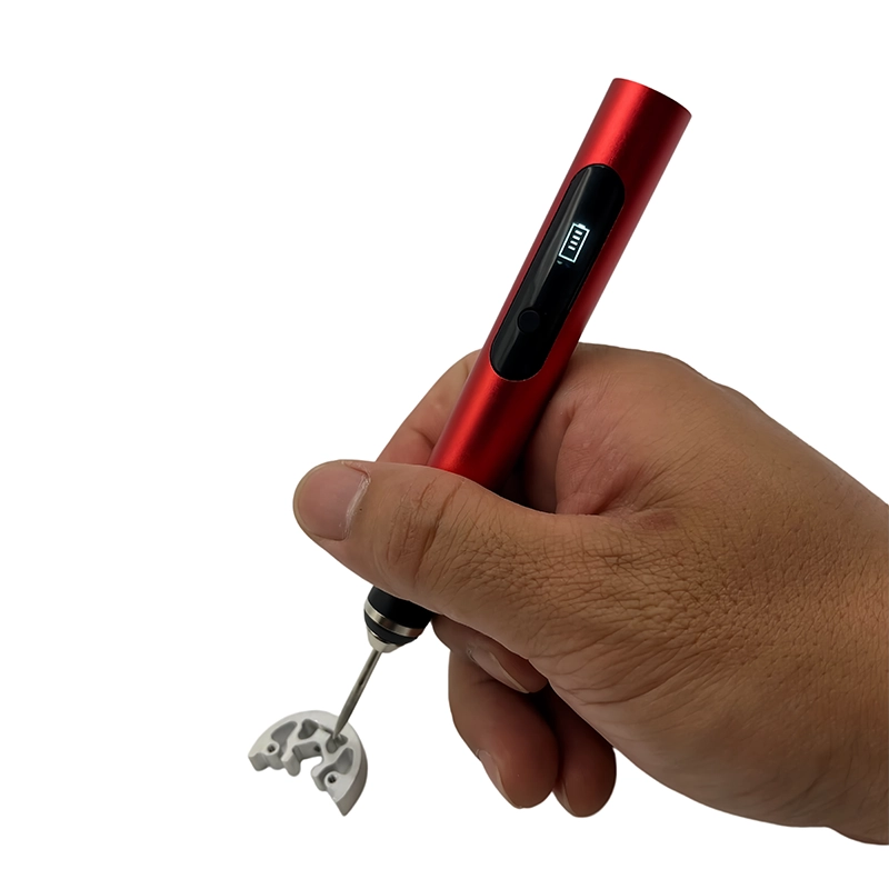
A compact rotary tool is useful when access, not surface area, is the problem. It can reach a small recess, hole entrance, curved support contact, internal seam or local repair area that a flat abrasive cannot reach. It should not replace hand sanding on every face. A powered accessory can oversize a hole, round a corner, heat a thermoplastic or remove more material than expected before the operator can stop.
Choose the smallest practical accessory and keep the contact moving. Use the accessory manufacturer’s permitted speed, light pressure and short passes, then stop to inspect. A larger wheel has a higher surface speed than a small point at the same RPM. A loaded abrasive can also change how it cuts. If the surface becomes glossy, smeared, whitened, chipped or unusually warm, stop and reassess the material, accessory and pressure rather than increasing force.
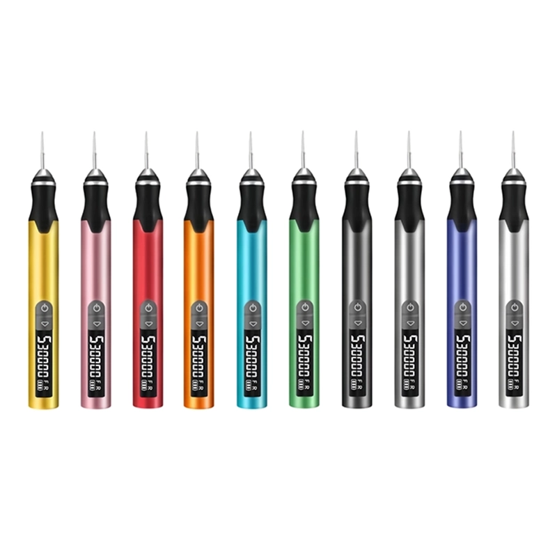
Current XOENAEN product records list D-102, 104 and 106 rotary platforms with three speed levels up to 18,000 RPM, and H101 and H102 platforms with five speed levels up to 30,000 RPM. The listed interface for these compact platforms is a 2.35 mm metal chuck. These are platform specifications, not universal settings for every filament, resin, accessory or geometry. A customer should approve the working setting on a representative printed coupon.
How do you protect edges and assembly fit?
Measure before sanding. Use the real pin, screw, bearing, cover or mating print as a functional check, and mark the actual interference rather than guessing from appearance. Remove material only from the marked area. After a short pass, clean the feature and test again. The correct stopping point is the specified fit, not the moment the component moves with no resistance.
Keep a crisp edge supported from the side where possible. A sanding block can preserve a straight boundary; a rotary point should approach the defect rather than sweep across the entire edge. If a part has a sealing face or a dimension that controls safety, use a controlled machining or reprint decision instead of promising that freehand sanding will hold a tight tolerance.
For repaired parts, decide whether the damage is cosmetic, lightly loaded or suitable only for a reprint. Prepare a repair groove or high spot with the minimum material removal, follow the adhesive or material maker’s preparation and cure instructions, and check alignment and function before cosmetic sanding. Polishing can improve appearance; it cannot prove that a load-bearing repair is safe.
Buyer checklist for a 3D print sanding kit
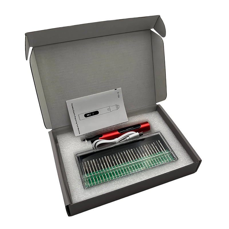
A practical OEM or workshop brief should name the printed materials, common defect types, part geometry, protected dimensions, target finish, operator skill and expected cycle. Specify whether the kit needs hand sheets, blocks, narrow abrasives, rotary accessories or a reciprocating option. For each accessory, record the job, shape, shank interface, permitted speed and replacement plan. Approve the exact pack-out on representative coupons, not only from a catalogue photograph.
Keep the final work instruction short enough to use at the bench: inspect and measure, mark the no-sand zones, remove the local high spot, clean, inspect under repeatable light, check the real mating feature and record any failure. This sequence helps a buyer compare a product platform on repeatability and control rather than accessory count alone.
Choose the sanding stage by the defect
| Stage | Use it for | Main risk | Stop when |
|---|---|---|---|
| Initial leveling | A proud support nub, seam ridge or local high spot | Gouging a thin wall or removing a datum | The high spot is level enough for the next stage |
| Intermediate blending | Making the repaired area match its surrounding texture | Rounding a boundary or changing a hole fit | The previous scratch pattern is controlled |
| Fine refinement | Reducing visible scratches before coating or assembly | Polishing over a defect or heating a plastic | The agreed surface requirement is met |
| Powered local work | Recesses, curves and small hard-to-reach defects | Oversize holes, heat, vibration or excess removal | The measured feature and surface pass inspection |
- Measure holes, edges, snap fits and mating faces before removing material.
- Select the first grit from the actual defect height and protected wall thickness.
- Use representative coupons for each filament, resin, accessory and speed combination.
- Specify accessory shape, shank interface, permitted speed and replacement plan for an OEM kit.
- Record inspection light, scratch pattern, fit check, stop criteria and any failure signs.
- View the referenced XOENAEN rotary-104 product →
- Read the complete 3D print finishing tools guide →
- Choose rotary tool speed for PLA, PETG, ABS and resin →
- Remove support marks from 3D printed parts →
- Compare rotary and reciprocating finishing tools →
- Select rotary bits for 3D print post-processing →
- Browse XOENAEN rotary tool platforms →
- XOENAEN editorial policy →
What is the first sanding grit for a 3D print?
Use the finest abrasive that can remove the actual high spot without excessive passes. The correct starting stage depends on the defect, wall thickness, material and protected dimensions, so qualify it on a representative coupon rather than using one universal grit.
How do I sand a 3D print without rounding its edges?
Mark no-sand zones, support the part, use a block on flat faces and make short local passes. Recheck the edge and mating feature after cleaning. Stop when the required geometry is preserved, even if the surface could become marginally smoother.
Can I use a rotary tool for every 3D printed surface?
No. A rotary tool is most useful for local access, recesses, holes and curves. Hand sanding often gives better control on broad or edge-critical surfaces. Powered work should use the approved accessory, speed and pressure on a representative coupon.
How do I know when to move to a finer grit?
Move on only when the previous scratch pattern is controlled and the high spot is removed. Clean the part and inspect under repeatable angled light. A finer grit should refine the surface, not hide a remaining ridge or change a functional feature.
What should an OEM sanding kit specification include?
Include materials, defects, geometry, protected dimensions, finish target, tool motion, abrasive shapes, grit stages, shank interface, permitted speed, sample coupons, inspection method, replacement parts, packaging and manual language.