Remove support marks in stages. First separate the support without levering against fragile walls, then trim only material that remains proud of the intended surface. Refine the witness mark with a controlled abrasive or suitable accessory, inspecting under side light after short passes. Protect edges and thin features. Stop when the contour is level; continued sanding can create a depression that is harder to correct.
Support-mark removal
Support-mark removal is the staged separation and refinement of support-contact residue until it meets the intended surface, without extending material removal into the model's designed contour.
What should be decided before removing support marks from 3D printed parts?
Inspect support-contact direction, wall thickness and nearby detail before bending, cutting or grinding anything. This first decision keeps reducing support nubs and witness marks without cutting into the intended model surface tied to a real task rather than a generic tool claim. Record what is known, what is assumed and which part of the decision still needs a sample. The practical boundary is to separate attached support from the final contour and choose staged removal based on material and access. If the work cannot be described that clearly, pause before choosing an accessory or publishing a recommendation.
Which work details control removing support marks from 3D printed parts?
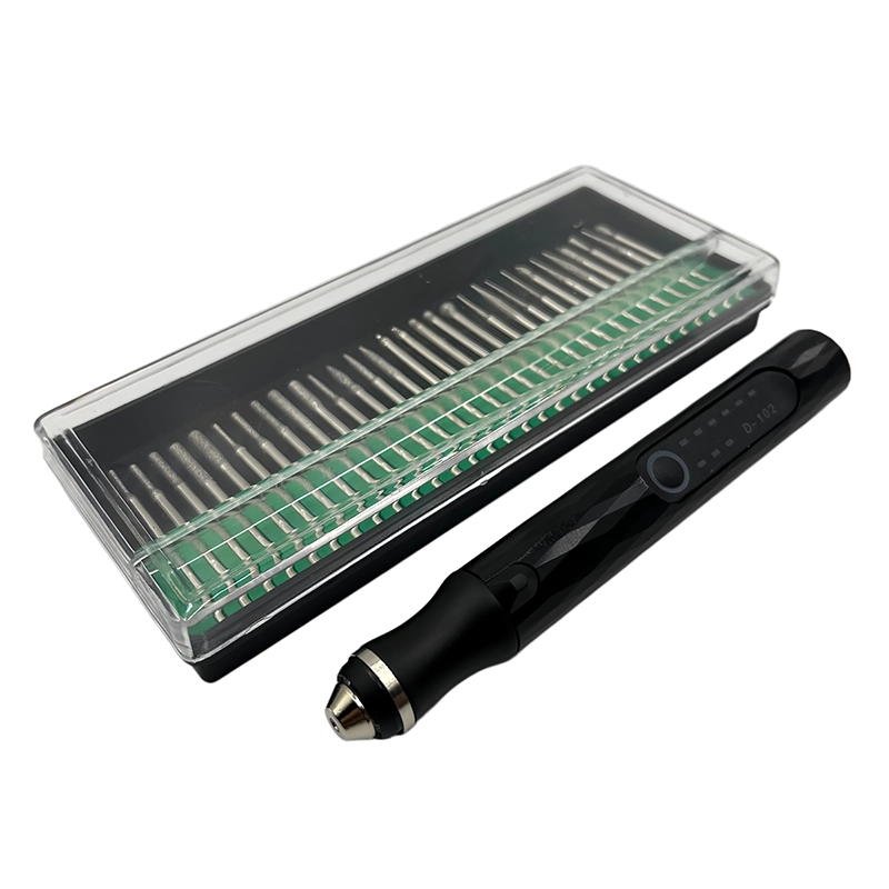
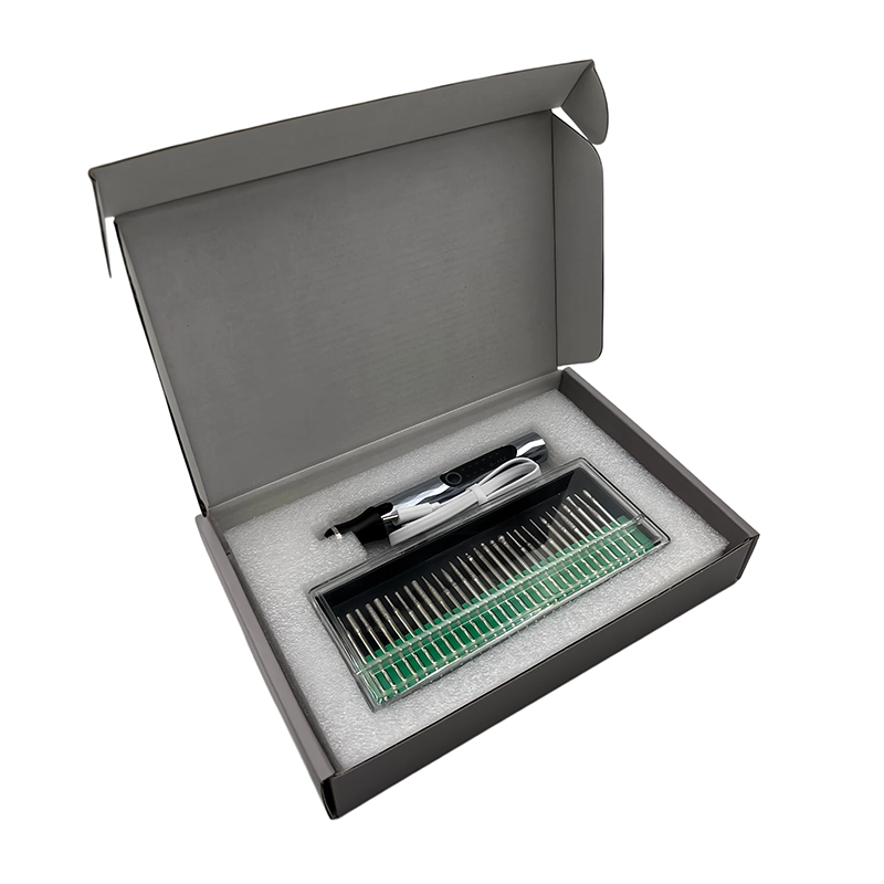
Separate the main support while backing the printed feature so leverage does not propagate a crack. Treat the check as part of one controlled workflow. The main failure to prevent is tear-out, gouges, rounded detail, heat damage and a low spot that requires filler rather than further sanding. Use a representative part, fastener or sample whenever possible, and change one variable at a time so the observation remains useful. A catalogue image can identify the referenced platform, but it does not prove the result on an untested material, device or production lot.
How should the tool or method be selected for removing support marks from 3D printed parts?
Trim proud residue in small increments and preserve a visible boundary to the intended contour. Selection should follow the working interface rather than accessory count or a broad marketing label. Note the contact geometry, available clearance, operator visibility and the point at which powered work should stop. Confirm the choice through side-light inspection and profile comparison after every removal and refinement stage. Retain the rejected option as well as the chosen one so later changes can be traced to a reason.
What setup reduces risk during removing support marks from 3D printed parts?
Choose an abrasive shape that reaches the witness mark without crossing edges or adjacent textures. Set up the work so movement, heat, debris and access can be observed. Support the item without loading a delicate feature, begin conservatively and inspect after a short interval. If the response differs from the sample or the expected condition, stop and reassess instead of compensating with more force, speed or time.
How should the first sample be checked?
Use side lighting and touch-free profile comparison between short refinement passes. A useful first pass answers a narrow question; it is not a demonstration of maximum removal or output. Compare the result with the baseline, clean the interface before inspection and write down the setting only with its material, accessory and geometry. This turns an isolated trial into evidence that can inform the next controlled step.
When should the operator stop and reassess?
Stop powered removal if heat, chatter, whitening or a developing low spot appears. The stop rule matters as much as the starting method. Stop when the tool loses alignment, the surface changes unexpectedly, heat or debris obscures the work, or the remaining geometry approaches its acceptance boundary. Escalate critical or uncertain conditions rather than converting a limited guide into an unsupported universal instruction.
What evidence belongs in the approval record?
Clean the surface and decide whether remaining defects need finer refinement, filler or acceptance as printed. For approval, keep the model or material identity, sample condition, method, observation, date and accountable decision together. The appropriate evidence is side-light inspection and profile comparison after every removal and refinement stage. Separate a product-existence record from a measured performance record, and state openly when a result still needs buyer or laboratory confirmation.
Which XOENAEN product reference supports this guide?
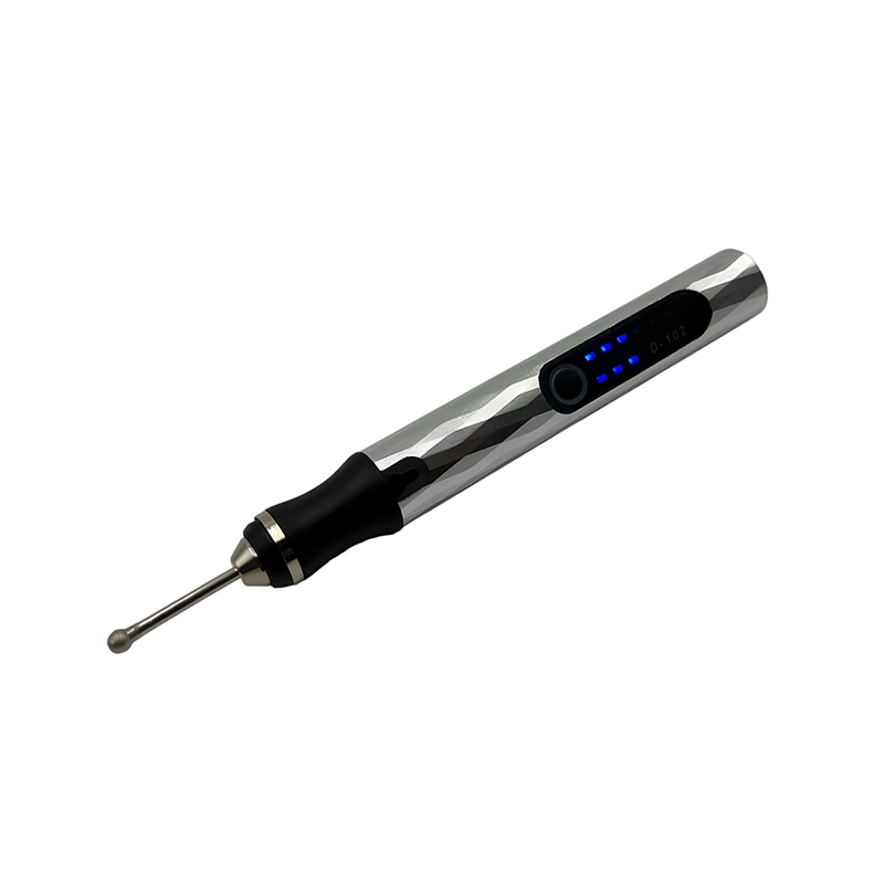
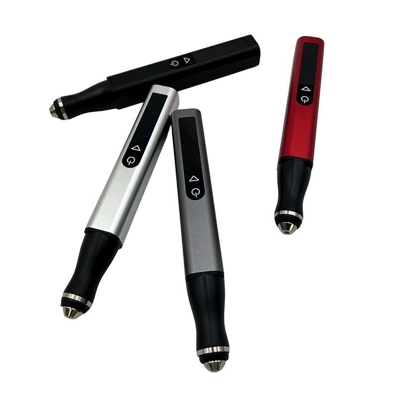
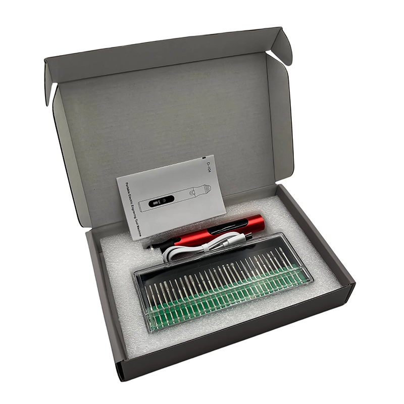
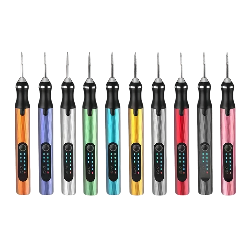
Record material and support geometry so future print-orientation changes can reduce finishing work at the source. The relevant first-party reference is the XOENAEN D-102 cordless rotary pen. It shows a documented product configuration that can anchor a discussion about removing support marks from 3D printed parts. Final suitability still depends on the exact task and sample because the catalogue does not establish compatibility with every device, polymer, fastener or finishing requirement.
Before closing the job, compare the result with the written requirement for removing support marks from 3D printed parts, clean the work area and retain any measurement, fit observation or unresolved exception. This final pause prevents a visually acceptable result from being mistaken for verified functional approval and gives the next operator or buyer a clear starting record.
Decision paths for removing support marks from 3D printed parts
| Path | Use when | Control |
|---|---|---|
| Proceed with a controlled sample | The application and boundary are documented for removing support marks from 3D printed parts | side-light inspection and profile comparison after every removal and refinement stage |
| Pause and clarify | Material, geometry, model or acceptance criteria remain uncertain | Prevent tear-out, gouges, rounded detail, heat damage and a low spot that requires filler rather than further sanding |
| Escalate or replace | The task is critical, damaged or outside the verified boundary | Use an approved specialist, replacement or documented alternative |
- Write the actual customer question for removing support marks from 3D printed parts
- Identify the exact product, material, fastener or geometry involved
- Define the acceptance boundary and the risk to prevent: tear-out, gouges, rounded detail, heat damage and a low spot that requires filler rather than further sanding
- Approve the sample method: side-light inspection and profile comparison after every removal and refinement stage
- Retain the model, accessory or bit map and the dated decision record
- Review the XOENAEN D-102 cordless rotary pen →
- Continue with the related rotary tool for 3d print support removal guide →
- Continue with the related clean resin print support marks guide →
- Open the complete 3D print finishing pillar guide →
- How XOENAEN separates product facts from test evidence →
- XOENAEN editorial and technical review policy →
- Discuss the application and sample plan →
What is the first decision in removing support marks from 3D printed parts?
Define the exact application and acceptance boundary first. For this guide, that means separate attached support from the final contour and choose staged removal based on material and access. Tool or accessory choice should follow that written requirement.
What is the main risk when removing support marks from 3D printed parts?
The main risk is tear-out, gouges, rounded detail, heat damage and a low spot that requires filler rather than further sanding. Use a representative sample, short controlled steps and frequent inspection instead of assuming one setting or configuration is universally safe.
How should a sample for removing support marks from 3D printed parts be verified?
Use side-light inspection and profile comparison after every removal and refinement stage. Record the applicable model or material, method, observations and decision so the result is not separated from the conditions that produced it.
Can one recommendation cover every case of removing support marks from 3D printed parts?
No. In removing support marks from 3D printed parts, device design, material, fastener, geometry, accessory and service condition can change the outcome. This guide provides a decision method; final suitability requires a representative check.
Which XOENAEN product is referenced for removing support marks from 3D printed parts?
For removing support marks from 3D printed parts, the first-party reference is the D-102 cordless rotary pen. Its catalogue page documents the platform and images used here, but it is not presented as proof of an untested application result.
What should a buyer record for removing support marks from 3D printed parts?
For removing support marks from 3D printed parts, record the requirement, chosen model or material, accessory or bit map, sample method, acceptance boundary, packaging or workflow revision, and the person responsible for the final approval.