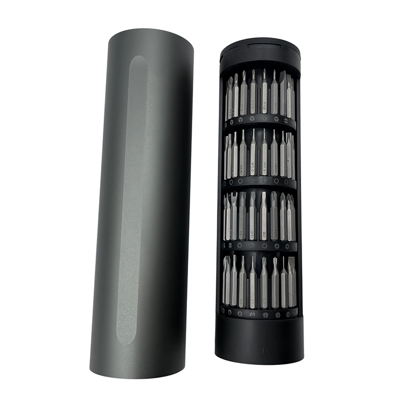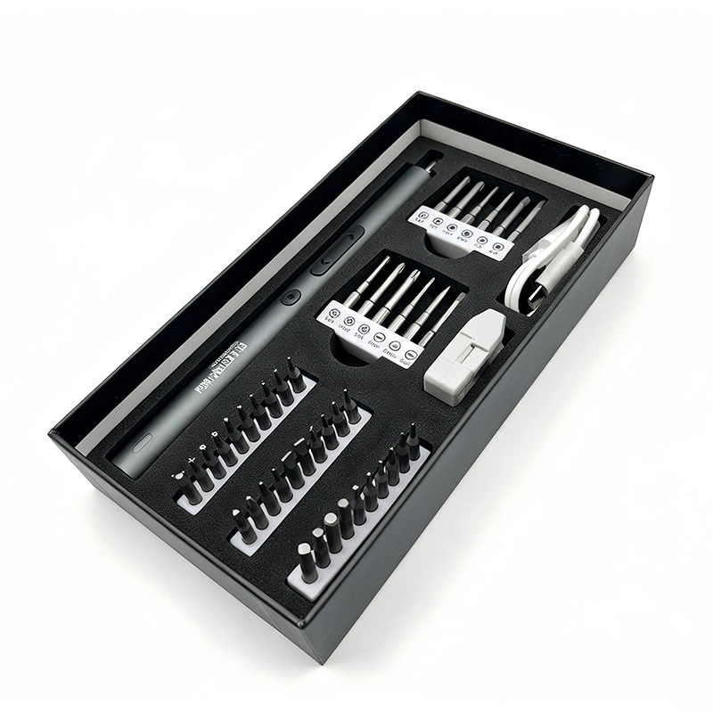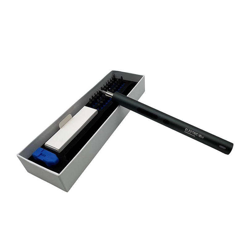
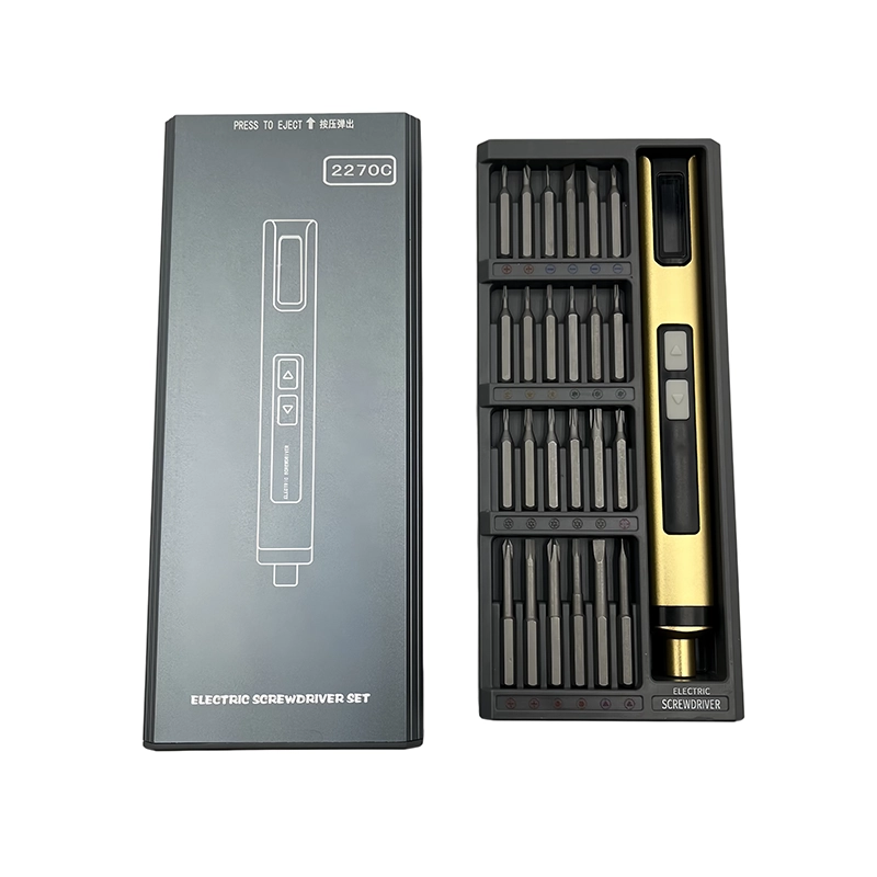
Use an electric screwdriver on cosplay prop electronics only after the printed shell, inserts, battery door and wire channels have been test-fitted. Support thin walls, start every screw by hand and use short low-speed travel in verified inserts. Stop before the shell compresses, then inspect cable clearance, removable battery access, switches and the prop's intended movement before use.
Cosplay electronics enclosure fit check
a dry assembly that verifies printed-wall support, inserts, wiring, battery access and screw lengths before decorative finishing or powered closure.
The practical setting for cosplay prop electronics assembly is building a wearable or handheld prop with printed shells, heat-set inserts, LEDs, switches, wires and a removable battery compartment. This article treats the powered driver as one controlled element in a larger repair, assembly or approval system. The goal is not maximum trigger time. The goal is to preserve thread condition, device evidence and a repeatable handoff from preparation through final verification.
How can makers use powered drivers on cosplay-prop electronics without crushing printed housings or wiring?
How can makers use powered drivers on cosplay-prop electronics without crushing printed housings or wiring? For cosplay prop electronics assembly, the useful answer begins with the service or assembly boundary, not with motor speed. Cosplay electronics enclosure fit check means a dry assembly that verifies printed-wall support, inserts, wiring, battery access and screw lengths before decorative finishing or powered closure. The operator must distinguish verified fastener travel from diagnosis, prying, drilling, calibration and electrical work that belongs to a different procedure. This boundary keeps the powered driver in the part of the task where repetitive rotation is useful and observable.
A sound cosplay prop electronics assembly decision also separates removal, free travel, thread engagement and final seating. Those phases do not carry the same risk. Removal may begin only after bit fit and support are proven. Free travel can often use controlled power. Thread engagement needs clear feedback, and final seating follows the product-specific instruction. Treating the entire joint as one trigger pull removes the inspection points that reveal a wrong screw, damaged thread or trapped component.
How should a bench be prepared for cosplay prop electronics assembly?
Preparation for cosplay prop electronics assembly starts with this action: Review the prop's materials, insert map and battery-removal plan Then Complete a dry fit and mark support points and cable channels Place the powered driver in a defined parking location and give removed hardware a separate, labeled area. A clean boundary prevents the tool, loose bit or customer screw from migrating into an exposed assembly. When batteries, boards, optics, seals or calibrated mechanisms are present, record exactly when the powered tool must leave the immediate work zone.
The fixture for cosplay prop electronics assembly should support the structure close to the fastener without blocking visibility. Photograph original routing and screw locations before anything moves. Clean the recess with a method approved for the product, inspect the candidate bit and quarantine damaged hardware. These steps take less time than recovering a stripped recess or investigating a mystery screw after reassembly.
What operating sequence works for cosplay prop electronics assembly?
The controlled sequence for cosplay prop electronics assembly is staged. First, Review the prop's materials, insert map and battery-removal plan Second, Complete a dry fit and mark support points and cable channels Third, Install electronics with the driver parked away from exposed wiring The first powered movement should be brief enough to stop while the original condition is still visible. Keep the driver aligned with the screw axis, avoid using the bit as a lever and release the control before repositioning the work.
Continue cosplay prop electronics assembly by following these closing steps: Hand-start case screws and use brief powered free travel only in sound inserts Finally, Check movement, controls, cable clearance and battery-door removal Account for every bit, screw, spacer and temporary fixture before power or function is restored. If the receiving thread does not accept the screw naturally, back out and investigate. Repeated trigger pulses are not a substitute for identifying contamination, wrong pitch, cross-threading or a shifted joint stack.
Why can cosplay prop electronics assembly fail even when the bit appears to fit?
The central failure path in cosplay prop electronics assembly is that powered seating can crush a thin printed wall, spin an insert, trap insulation or close a battery door that no longer releases. A tip can enter a recess and still be the wrong size, worn, too short or poorly aligned. Before powered travel, verify that the bit reaches its designed depth, does not rock and clears adjacent parts. Observe the screw from a second angle whenever the housing, fixture or operator's hand can hide side load.
For cosplay prop electronics assembly, the four application controls are specific: dry-fit shells and screw lengths before paint or electronics installation; support printed walls near each fastening point; use hand engagement to verify every insert; and inspect wire channels and battery access before the seam closes. Each control blocks a different error path. No single claim about torque, runtime, steel grade or accessory count replaces them. If one control cannot be demonstrated on representative hardware, the task remains unapproved even when the driver runs normally on an unloaded bench.
What stop rule protects cosplay prop electronics assembly?
The explicit stop signal for cosplay prop electronics assembly is: a printed wall flexes, an insert rotates, insulation is pinched or the battery door changes fit. At that point, release the trigger, keep the original condition visible and decide whether the bit, screw, thread, fixture or procedure needs correction. Do not add downward force or speed simply because the expected movement did not occur. A stop rule is useful only when every operator can recognize it before damage becomes the new condition.
Acceptance for cosplay prop electronics assembly is equally concrete: the shell aligns without crushing, wires remain clear, controls and lights work and the battery can be removed by the intended method Check the surrounding assembly, not only the screw head. Enclosures should settle without forced gaps, moving parts should retain clearance, cables and seals should remain in their documented positions, and any required functional or calibration check should follow the accountable maker's procedure. Record exceptions rather than hiding them under final assembly.
Which two approaches should be compared for cosplay prop electronics assembly?
For cosplay prop electronics assembly, Solid molded enclosure is best understood this way: may distribute clamp load through designed bosses and ribs. By comparison, Thin printed prop shell is best understood this way: often needs local support and a lower-compression stop condition. Neither label is automatically safer or faster. Choose from access, screw condition, receiving material, cycle count, operator visibility and the cost of a mistake. Record why the selected approach fits this exact application instead of copying a setting from an unrelated device.
Let the printed geometry and insert condition define the stop point; motor sound is not a reliable measure of shell compression. That recommendation for cosplay prop electronics assembly turns a broad tool feature into a documented decision. During sample review, evaluate the installed bit, actual hardware, workholding and operator sequence together. A free-spinning demonstration can show that the motor works, but it cannot prove control at a shallow recess, plastic boss, threaded insert, gasketed joint or crowded electronic assembly.
What should a buyer specify for cosplay prop electronics assembly?
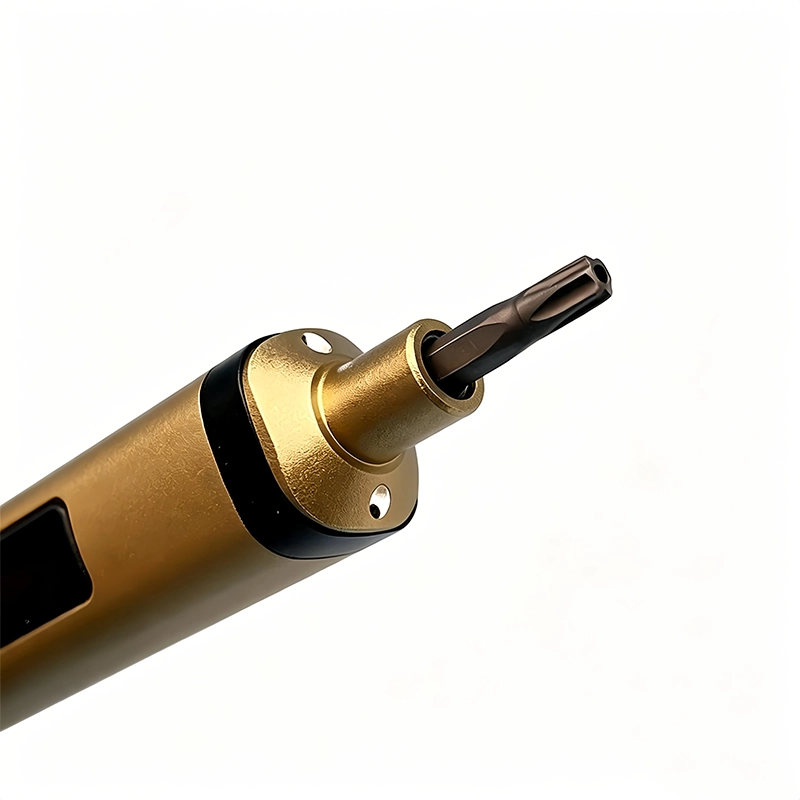
For cosplay prop electronics assembly, sample the shortest and longest screw locations, insert engagement, low-speed start and access around the actual prop electronics. The RFQ should name target devices or joints, screw profiles and sizes, working lengths, expected daily cycles, charging pack-out, case layout, manual languages and sample quantity. Compatibility claims need a model list and an approval method. Numerical claims need the test condition, sample count, acceptance limit and record owner.
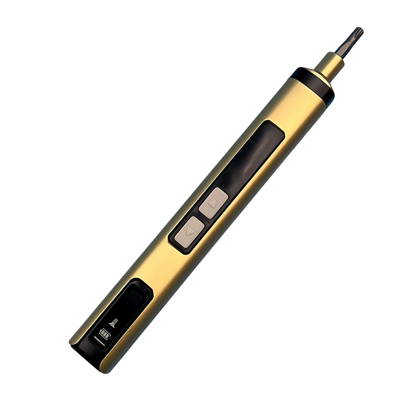
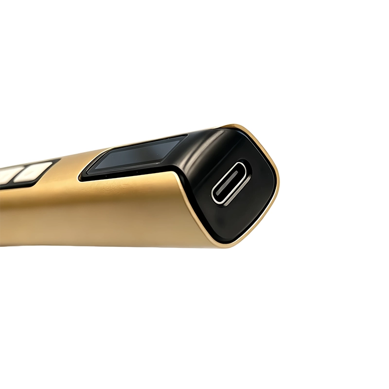
The sample plan for cosplay prop electronics assembly should inspect appearance, controls, bit fit, installed-bit behavior, charging, indicator states, case organization, labels, instructions and representative screw work. Retain the approved sample and its bit map. If the motor, battery, control board, cable, bit source, case insert or instruction changes, assess the effect before the revised item enters production or replaces field stock.
How should cosplay prop electronics assembly influence maintenance and training?
Training for cosplay prop electronics assembly should show the real fixture, screw groups, parking location, hand-to-power transition and stop signal. “Use carefully” is not an instruction. A repeatable instruction names the profile, working length, support point, rotation phase and condition that requires escalation. Supervisors can then observe the process and separate a tool problem from a mapping, material, training or product-design problem.
Maintenance records for cosplay prop electronics assembly should distinguish worn bits, holder contamination, control faults, charging issues, abnormal sound, dropped tools and application damage. Trend the categories rather than combining them as “driver problems.” A recurring pattern may call for a replacement interval, clearer label, different accessory, revised fixture or supplier corrective action. Evidence from the workbench is more valuable than adding unverified claims to the package.
What evidence supports guidance for cosplay prop electronics assembly?
This cosplay prop electronics assembly guide uses the stated customer question, a task-level failure analysis, the linked official guidance and the current XOENAEN catalogue record for the selected product platform. It does not infer universal device compatibility, certification, a customer result or a torque value that is absent from the model record. Representative hardware and the accountable product procedure remain the basis for approval.
The methodology for cosplay prop electronics assembly connects each recommendation to an observable condition: bit engagement, alignment, receiving material, workholding, powered response, stop signal and post-work acceptance. Keep photographs, sample identifiers, revisions and deviations with the decision. This creates an answer that another technician or buyer can audit instead of relying on a generic “best tool” statement that changes meaning from one joint to another.
Solid molded enclosure compared with Thin printed prop shell for cosplay prop electronics assembly
| Approach | Best use | Primary control |
|---|---|---|
| Solid molded enclosure | may distribute clamp load through designed bosses and ribs | dry-fit shells and screw lengths before paint or electronics installation |
| Thin printed prop shell | often needs local support and a lower-compression stop condition | support printed walls near each fastening point |
- Define the customer question for cosplay prop electronics assembly: How can makers use powered drivers on cosplay-prop electronics without crushing printed housings or wiring?
- Document the real application boundary: building a wearable or handheld prop with printed shells, heat-set inserts, LEDs, switches, wires and a removable battery compartment
- Verify the first powered control: dry-fit shells and screw lengths before paint or electronics installation
- Verify the second powered control: support printed walls near each fastening point
- Approve representative hardware against XOENAEN 50-in-1 electric screwdriver set
- Retain the bit map, charging pack-out, stop rule and revision owner for cosplay prop electronics assembly
- XOENAEN 50-in-1 electric screwdriver set →
- XOENAEN OEM and ODM process →
- Manufacturing and quality control →
- Read the related electric-screwdriver-guitar-pedal-kit-assembly guide →
- Read the related electric-screwdriver-motorized-scale-model-assembly guide →
- Continue with the electric-screwdriver-custom-pc-motherboard-cooler-build topic →
- How XOENAEN presents quality evidence →
- Read the related choose-precision-electric-screwdriver guide →
How is local heat avoided on a printed cosplay shell?
Before cosplay prop electronics assembly, confirm the exact product boundary, fastener map and this first control: dry-fit shells and screw lengths before paint or electronics installation. A physically fitting bit alone does not authorize the work.
When must cable routing be checked before prop closure?
The specific powered-rotation concern during cosplay prop electronics assembly is that powered seating can crush a thin printed wall, spin an insert, trap insulation or close a battery door that no longer releases. Short runs and deliberate inspection points preserve time to detect that change.
What proves a removable prop battery door still fits?
Release the trigger during cosplay prop electronics assembly as soon as a printed wall flexes, an insert rotates, insulation is pinched or the battery door changes fit. Do not compensate with more speed, pressure or repeated cycling.
Why should cosplay enclosure inserts be tested before final paint?
For cosplay prop electronics assembly, Solid molded enclosure may distribute clamp load through designed bosses and ribs, while Thin printed prop shell often needs local support and a lower-compression stop condition. Select the method from the joint condition and consequence of error.
Which sample records should a buyer retain for cosplay prop electronics assembly?
A buyer approving cosplay prop electronics assembly should document sample the shortest and longest screw locations, insert engagement, low-speed start and access around the actual prop electronics. The approved sample, bit map and revision record should remain linked to the purchase specification.
Which observable result closes the work on cosplay prop electronics assembly?
Completion of cosplay prop electronics assembly requires this observable result: the shell aligns without crushing, wires remain clear, controls and lights work and the battery can be removed by the intended method Installed screws alone are not evidence that the surrounding product is correctly restored.