Measure the board hole and pin, then correct only mapped high spots around the circumference. Support the pin diameter, lead chamfer and supporting base with a support block surrounding the pin base without touching the working diameter. Control axis support, diameter checks, chamfer length and debris containment. Stop if the pin develops a flat, bends under contact or the board begins to rock after seating.
refine 3D printed PCB fixture locating pin
refine 3D printed PCB fixture locating pin is a controlled process for fitting a PCB onto a printed assembly or inspection fixture that protects pin axis, center location and designed board clearance and releases the part only when the board seats to its datum with the approved clearance and repeatable registration.
Making the board drop on more easily can reduce locating repeatability; insertion force and positional result must be considered together. This guide treats refine 3D printed PCB fixture locating pin as a specific workshop decision around fitting a PCB onto a printed assembly or inspection fixture. It does not assume that one accessory, speed or motion is safe for every polymer, resin, wood or metal. The actual part, its drawing and the customer’s acceptance reference remain the final authority.
How can a printed locating pin be corrected without shifting board registration?
Measure the board hole and pin, then correct only mapped high spots around the circumference. Begin by cleaning and photographing the pin diameter, lead chamfer and supporting base. Mark pin axis, center location and designed board clearance as a no-change reference, then test a single short intervention in an accessible zone. For refine 3D printed PCB fixture locating pin, clean the work again before evaluating it; dust, loaded media and temporary heat can disguise both scratches and missing material.
What makes this geometry different from a general sanding job?
The job is fitting a PCB onto a printed assembly or inspection fixture, and the working surface is the pin diameter, lead chamfer and supporting base. Those details determine where force travels and which mistake matters. A generic instruction such as use light pressure cannot protect pin axis, center location and designed board clearance. A usable work instruction instead names the support, approach direction, maximum worked zone and the inspection that must follow every short pass.
Which motion should be used for refine 3D printed PCB fixture locating pin?
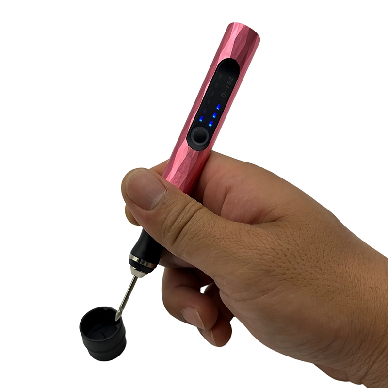
The proposed motion is measured hand sizing with isolated rotary burr removal. a guided fine abrasive sleeve turned by hand offers a useful reference because the operator can feel initial contact, while a fine rotary point used only on an entrance burr may improve access or consistency after the contact area is understood. Compare the two on equivalent defects rather than assuming powered work is automatically faster once cleanup, inspection and rejected parts are counted.
How should the workpiece be supported before contact?
Use a support block surrounding the pin base without touching the working diameter. Support should sit close enough to the worked zone to prevent vibration but must not preload the feature being checked. Confirm that clamps, fingers and cables remain outside the tool path. For refine 3D printed PCB fixture locating pin, the fixture is part of the approved method: changing it can change vibration, apparent fit and how much material the media removes.
Which variables deserve a first-piece record?
Record axis support, diameter checks, chamfer length and debris containment, together with the part material, print orientation or stock form, accessory identity, clean starting condition and contact sequence. Photograph the setup from an angle that shows the protected feature. A buyer comparing kits should ask whether controls can be repeated by another trained operator, not only whether the demonstration sample looked acceptable once.
When should powered finishing stop immediately?
Stop when the pin develops a flat, bends under contact or the board begins to rock after seating. Isolate the tool, remove debris and compare the area with its starting image before making another decision. Added speed or pressure cannot restore geometry already removed. The stop signal belongs on the bench instruction and, where relevant, in the product manual because it is more actionable than a broad warning to avoid damage.
How do the hand and powered methods compare?
a guided fine abrasive sleeve turned by hand usually provides better tactile feedback and a simple dimensional reference. By contrast, a fine rotary point used only on an entrance burr can help with reach or repeated short strokes. For refine 3D printed PCB fixture locating pin, compare edge condition, heat, debris, setup time, inspection time and consistency across at least two representative samples. Keep both options available when the feature changes across the job.
What inspection closes the job?
Use the production board or gauge plate, pin measurement and datum seating check. The acceptance statement is explicit: the board seats to its datum with the approved clearance and repeatable registration. Perform the check on a clean part returned to a stable temperature. Cosmetic improvement is not enough where a fit, seal, motion or datum is involved. If the required reference is unavailable, hold the part for review rather than polishing until the original condition can no longer be seen.
Which kit details matter to a European or North American buyer?
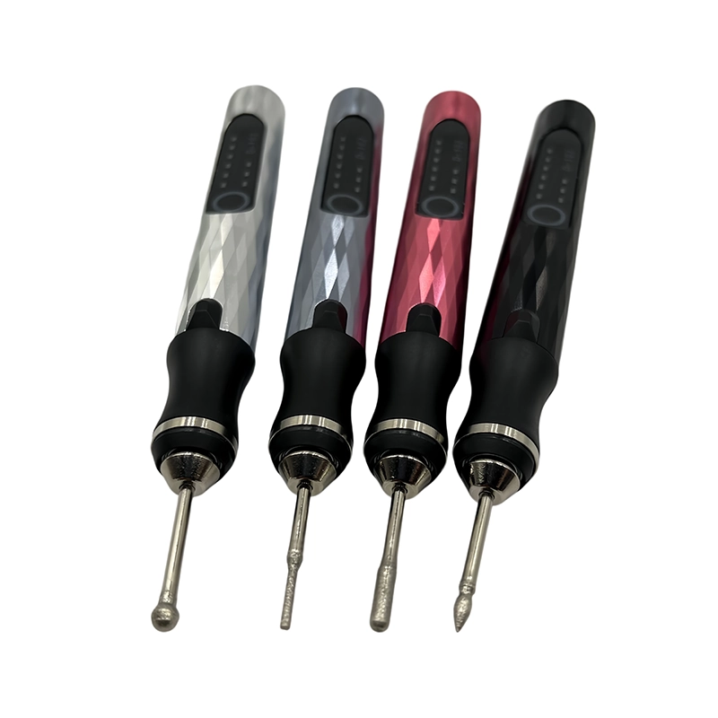
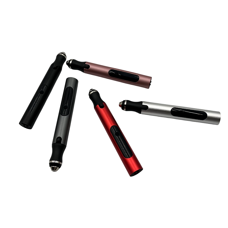
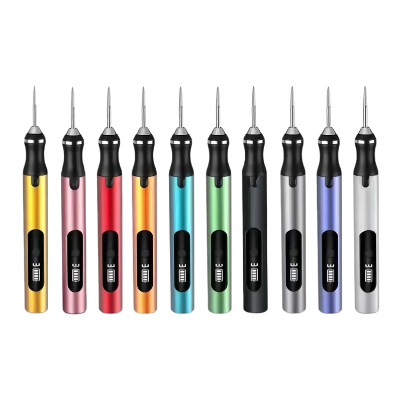
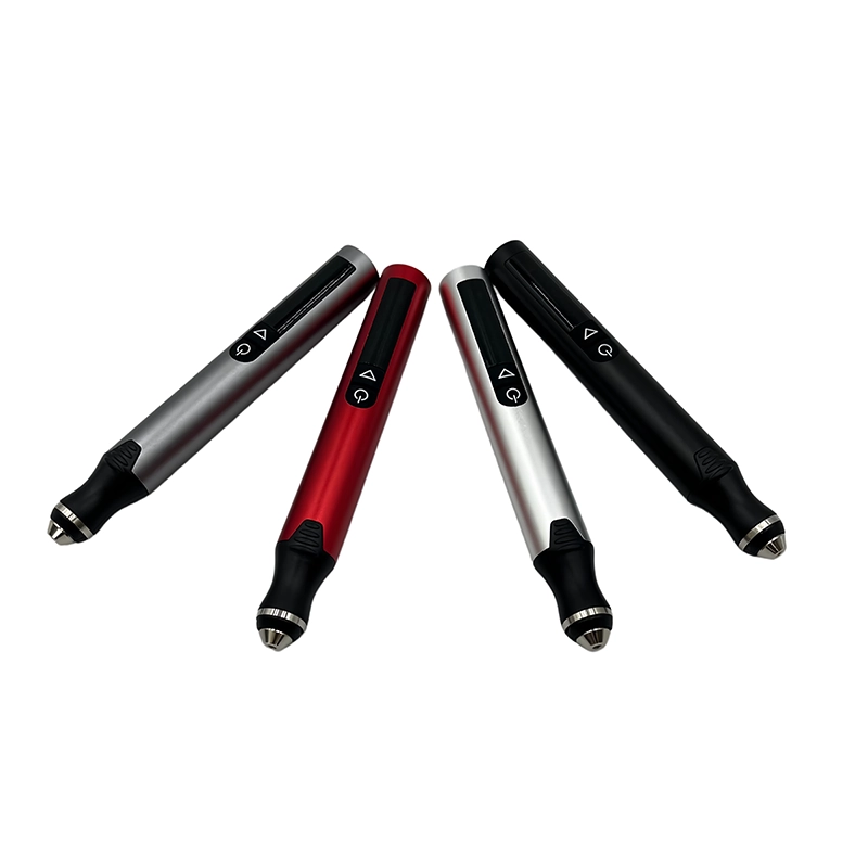
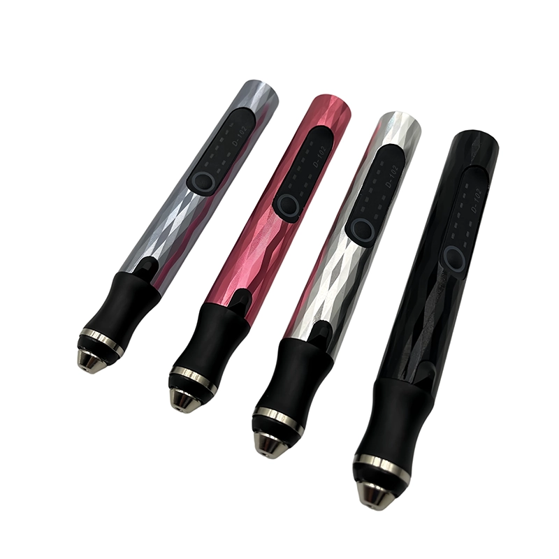
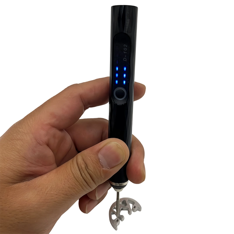
The D-102 cordless electric engraving pen is a current XOENAEN catalogue reference, not proof of universal suitability for refine 3D printed PCB fixture locating pin. Review the exact control layout, compatible shank or pad interface, included media identity, charging configuration, case labeling and availability of replacement consumables. Market documentation and electrical review must match the final sellable configuration rather than a development photograph.
What belongs in the OEM or wholesale project brief?
Provide board-hole tolerance, datum scheme, pin height and required fixture repeatability. Add target markets, expected quantity, packaging language, accessory map, replacement pack, visual limits and sample timing. The brief should identify who approves the first article and which workpiece proves the claim. This keeps sales copy, instructions and quality checks aligned with evidence instead of expanding a single workshop result into a universal promise.
How can the method sound like a real shop instruction?
Write the sequence with observable verbs: inspect, mark, support, install, make one pass, stop, clean and measure. Name the pin develops a flat, bends under contact or the board begins to rock after seating as the rejection trigger and the board seats to its datum with the approved clearance and repeatable registration as the release condition. Retain one accepted sample or image set. Reapprove the method after a material, accessory, fixture or product revision rather than relying on memory from the original trial.
For the final record, link refine 3D printed PCB fixture locating pin to the exact part revision, D-102 cordless electric engraving pen configuration, accessory identity and inspection reference. Making the board drop on more easily can reduce locating repeatability; insertion force and positional result must be considered together. A concise record of what was protected, what was changed and what proved completion is more useful to future operators—and to search readers—than generic claims about effortless professional results.
a guided fine abrasive sleeve turned by hand compared with a fine rotary point used only on an entrance burr
| Method | Useful when | Main control |
|---|---|---|
| a guided fine abrasive sleeve turned by hand | Tactile feedback or a hard reference is needed | the production board or gauge plate, pin measurement and datum seating check |
| a fine rotary point used only on an entrance burr | Access or repeated short strokes matter | axis support, diameter checks, chamfer length and debris containment |
- Define the exact task: fitting a PCB onto a printed assembly or inspection fixture
- Protect pin axis, center location and designed board clearance
- Use a support block surrounding the pin base without touching the working diameter
- Control axis support, diameter checks, chamfer length and debris containment
- Stop if the pin develops a flat, bends under contact or the board begins to rock after seating
- Approve only when the board seats to its datum with the approved clearance and repeatable registration
- D-102 cordless electric engraving pen →
- 3D print finishing tool selection guide →
- Sanding an Inside Corner of a 3D Printed Enclosure →
- Tuning a 3D Printed Captive-Nut Pocket Without Spin →
- Cleaning a Miniature Base Rim Without Losing Ground Texture →
- Application planning →
- OEM and ODM development →
- XOENAEN editorial policy →
What is the first measurement for refine 3D printed PCB fixture locating pin?
Start with the production board or gauge plate, pin measurement and datum seating check and record the untouched condition of the pin diameter, lead chamfer and supporting base. That establishes whether the problem is real, where it is located and which feature must remain unchanged before any abrasive or cutting accessory is selected.
Why is measured hand sizing with isolated rotary burr removal considered for this job?
That motion can match the access and contact pattern of fitting a PCB onto a printed assembly or inspection fixture, but it still requires a support block surrounding the pin base without touching the working diameter. The choice is provisional until a representative sample proves that pin axis, center location and designed board clearance remains intact.
Which visible warning ends refine 3D printed PCB fixture locating pin?
End the pass when the pin develops a flat, bends under contact or the board begins to rock after seating. Clean and inspect before deciding whether a different hand method, accessory or fixture is needed; continuing with more force would hide the cause and can remove functional geometry.
Does the rotary-102 platform guarantee refine 3D printed PCB fixture locating pin?
No. The rotary-102 is a real XOENAEN catalogue reference for discussing refine 3D printed PCB fixture locating pin, not a universal application claim. Suitability depends on the pin diameter, lead chamfer and supporting base, the selected accessory, workholding, instruction and the acceptance sample supplied for this exact project.
What proves a sample passes refine 3D printed PCB fixture locating pin?
The cleaned, stable part must meet this condition: the board seats to its datum with the approved clearance and repeatable registration. Use the stated gauge, mating item, motion test, lighting reference or dimensional check rather than approving the part from a general impression that it looks smoother.
What should the buyer send for a refine 3D printed PCB fixture locating pin quotation?
Provide board-hole tolerance, datum scheme, pin height and required fixture repeatability. Also state volume, market, required documentation, preferred pack-out and the first-article sample that will be used to approve the proposed rotary or reciprocating configuration.