When moving a breadboard project into a final enclosure, treat the mechanical build as a new verification stage. Confirm power isolation, board supports, terminal access, wire bend radius and screw clearance before using a driver. Start fasteners by hand, keep powered rotation away from exposed conductors and finish with continuity, polarity, strain-relief, enclosure and functional checks defined for the project.
breadboard-project final enclosure assembly powered-work boundary
The documented point at which verified electric screw travel ends and hand starting, component handling, inspection, testing or another accountable procedure begins during breadboard-project final enclosure assembly.
For breadboard-project final enclosure assembly, useful powered rotation begins only after the operator can name the screw, bit, receiving material, nearby risks and stopping point. The practical setting is transferring a proven prototype into a project box with a permanent board, terminal blocks, switches, cable glands and mounting hardware. This guide treats the electric screwdriver as one controlled part of a documented repair or DIY process; it does not replace the product manual, electrical safety work, diagnosis, sealing verification or final functional evidence.
What decision should come first for breadboard-project final enclosure assembly?
What changes when a working breadboard circuit is transferred to a screwed final enclosure with boards, terminals and cable restraints? The useful answer starts with the product procedure and the exact joint, not the motor setting. The real setting is transferring a proven prototype into a project box with a permanent board, terminal blocks, switches, cable glands and mounting hardware. Identify which screws are intended service points, what sits below them and where powered work must stop. This prevents a physically fitting bit from being mistaken for authorization, compatibility or proof that the complete repair can be restored safely.
Separate breakaway, free travel, thread starting and final seating. They are four different decisions. A powered driver can shorten repeated rotation after engagement is known, but it cannot identify a mixed screw, feel a trapped cable, inspect a seal or decide that a distorted part should be pulled into place. For breadboard-project final enclosure assembly, the practical recommendation is simple: Do not treat a working breadboard as proof that the enclosed product is mechanically or electrically acceptable.
How should the bench be prepared for breadboard-project final enclosure assembly?
Begin by disconnect and verify the project’s safe state. Then dry-fit boards, terminals, switches and cables. Give the driver a fixed parking place beyond the opened assembly and give screws a labeled location that preserves sequence and length. Lighting must show the screw axis and surrounding component, while the fixture supports the structure close to the fastener without hiding movement or transferring pressure into a display, board, seal, gear or finished surface.
For breadboard-project final enclosure assembly, photograph the original condition before hardware moves. Reconcile tools, bits and fasteners at every layer change. When the task involves batteries or electronics, follow the accountable safe-state and ESD instructions rather than improvising. When the task involves a child-accessible toy, control every loose part and leave product-safety decisions to the responsible maker or qualified process; a blog is not a substitute for that assessment.
Which operating sequence keeps breadboard-project final enclosure assembly observable?
The sequence is staged: disconnect and verify the project’s safe state; dry-fit boards, terminals, switches and cables; and hand-start verified mechanical fasteners. The first powered movement should be short enough that the screw head, joint and nearby parts can still be inspected in their original relationship. Keep the tool on axis, release before repositioning and never use a bit as a pry bar, locating pin or method for pushing the assembly into place.
Continue by use powered free travel only outside exposed-conductor zones. Finish by perform documented continuity, polarity, insulation and function checks as applicable. Account for every screw, bit, spacer, washer and temporary fixture before power or function returns. If a thread does not start naturally, back it out and inspect profile, pitch, contamination, receiving material and alignment. Repeated trigger pulses merely erase evidence when the real problem is a wrong fastener or shifted joint stack.
Why can breadboard-project final enclosure assembly go wrong even when the bit fits?
The main failure path is that a screw or standoff can contact a conductor, while compressed wires or unsupported terminals can create faults that never appeared on the open breadboard. A tip can enter a recess while still being undersized, worn, tilted or too long for the surrounding clearance. Prove full-depth engagement by hand, view the axis from a second angle and use the shortest working length that reaches without scraping adjacent features. If the recess is contaminated or damaged, clean or escalate it instead of increasing pressure.
Four controls define this job: freeze the wiring diagram and enclosure BOM; measure screw and standoff clearance to conductors; separate mechanical fastening from energized electrical checks; and inspect cable bend and strain relief before closure. Each blocks a different failure. Accessory count, advertised speed and battery capacity do not replace these checks. A tool sample remains unapproved when one of these conditions cannot be demonstrated on representative hardware, even if the unloaded driver sounds normal and the case looks complete.
Which two approaches should be compared for breadboard-project final enclosure assembly?
Open breadboard proof shows the circuit concept but not final strain, clearance or enclosure behavior. By contrast, Closed-enclosure verification adds mechanical support, wiring, access and thermal conditions to the functional test. Neither label is universally safer. Choose by access, screw condition, receiving material, visibility, repetition and the consequence of an error. Document why the selected approach fits this joint instead of copying a torque mode or hand position from another phone, tablet, toy or maker project.
A representative breadboard-project final enclosure assembly trial should combine the installed bit, actual screw, support method, nearby components and operator sequence. Free-spinning the driver can show that its motor and controls respond, but it cannot prove clean engagement in a shallow recess or acceptable seating into plastic, an insert, a gasketed cover or a light bracket. The real comparison therefore ends with the finished joint and its acceptance checks.
When should powered rotation stop during breadboard-project final enclosure assembly?
The observable stop signal is: a fastener approaches a conductor, wire insulation is pinched, terminal access changes or the mechanical drawing no longer matches the wiring. Release immediately, keep the condition visible and decide whether the bit, screw, thread, fixture, part or work instruction is wrong. Do not add force because the expected movement did not occur. A useful stop rule names something the operator can see, hear or feel early enough to protect the original assembly.
The matching acceptance condition is: clearances and strain relief match the design, no hardware is loose and the completed project passes its documented electrical and functional checks. Look beyond the screw head. Enclosures should meet without forced gaps, cables and seals should remain in their routed positions, mechanisms should retain clearance and any functional check should follow the accountable product or project procedure. Record a deviation rather than hiding it beneath a fully assembled cover.
What should a buyer specify for breadboard-project final enclosure assembly?
For sample approval, evaluate precision profiles, insulated work boundaries, low-speed control and case organization against the final enclosure hardware rather than the temporary breadboard. The RFQ should name target models or joints, fastener profiles and sizes, working lengths, expected workload, charging pack-out, case layout, manual languages and sample quantity. Compatibility claims need a model list and method. Numerical claims need test conditions, sample count, limits and a record owner instead of an isolated marketing number.
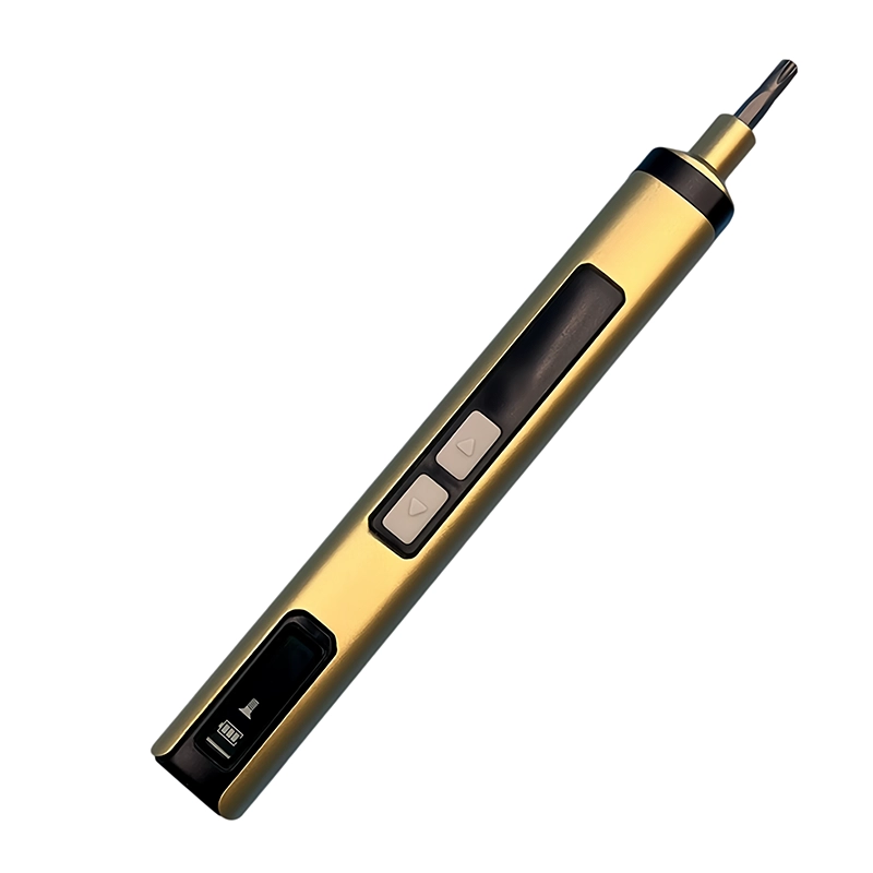
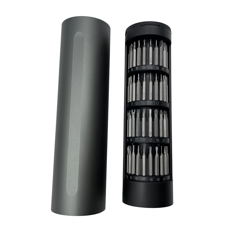
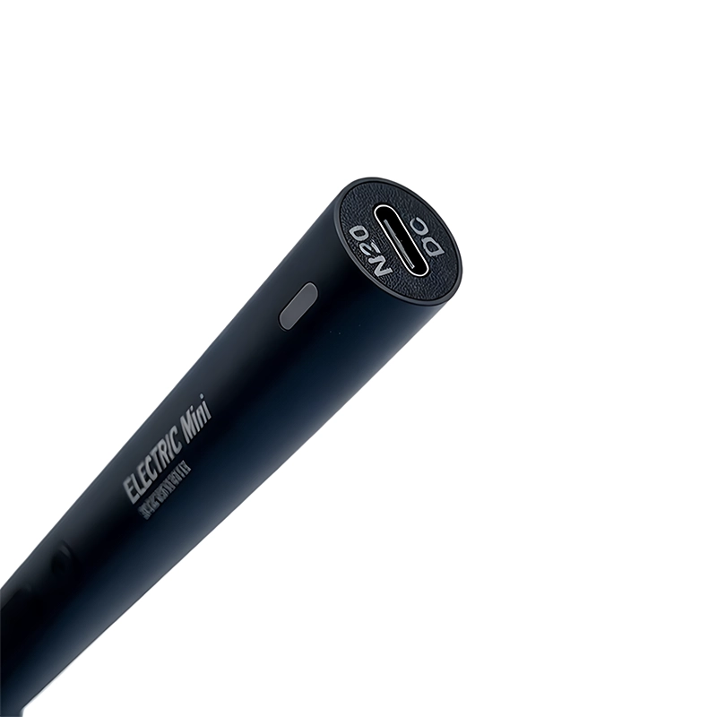
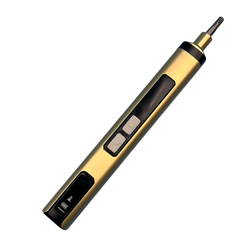
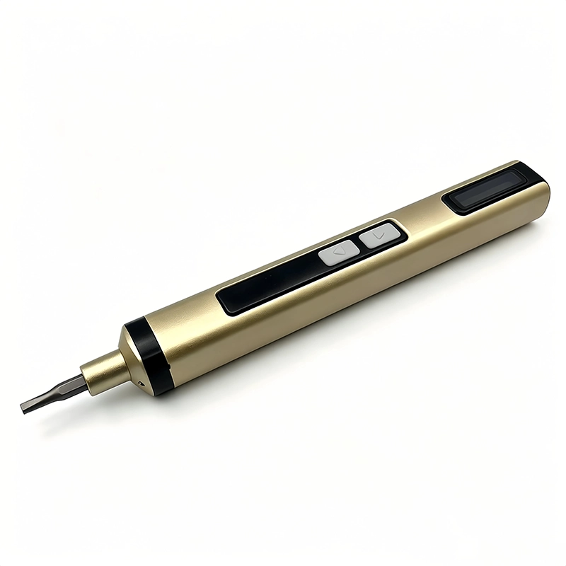
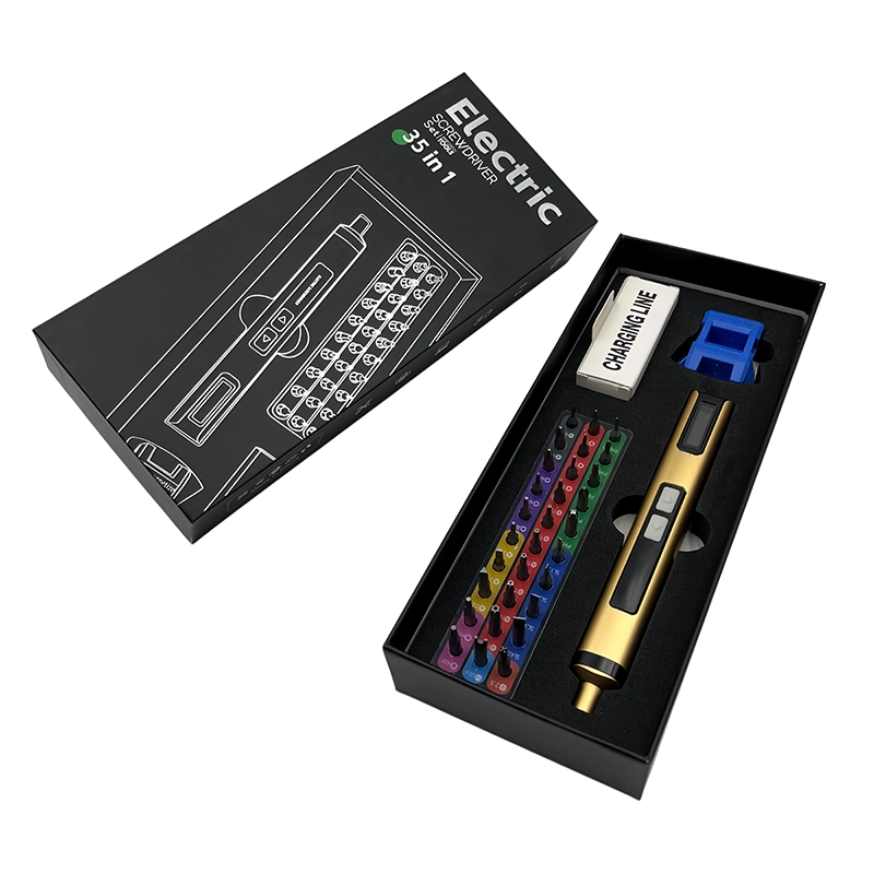
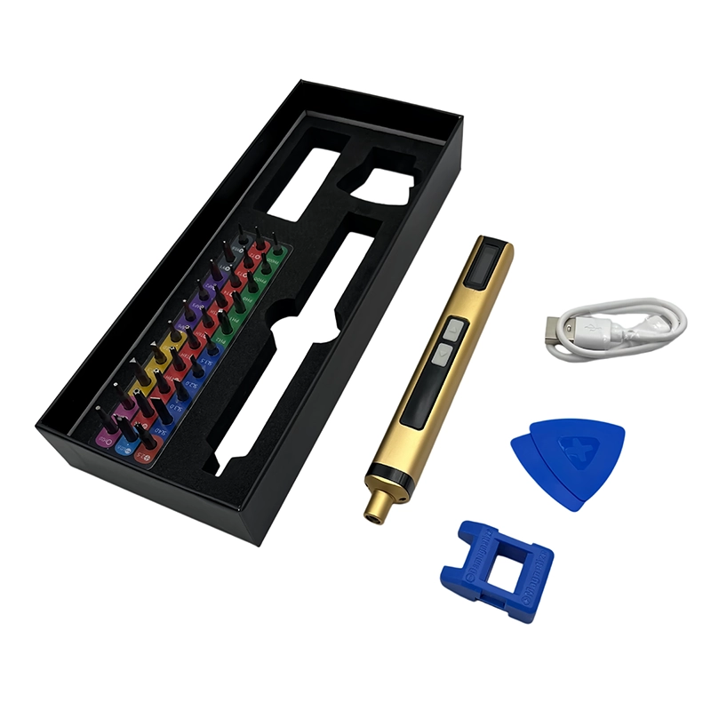
Inspect the physical driver, installed-bit behavior, charging items, indicators, case organization, labels, instructions and representative screw work as one system. Retain the approved sample and its bit map. If the motor, battery, control board, bit source, cable, case insert or instructions change, assess the effect on breadboard-project final enclosure assembly before the revision enters production or replaces field stock.
How should breadboard-project final enclosure assembly shape training and maintenance?
Training for breadboard-project final enclosure assembly should show the actual fixture, screw groups, parking location, hand-to-power transition and the stop signal. “Use carefully” is not a reproducible instruction. Name the bit, working length, support point, powered phase and condition that requires escalation. A second technician should be able to follow the record without relying on the first operator’s memory or an unlabelled photograph.
Maintenance records supporting breadboard-project final enclosure assembly should distinguish worn tips, contaminated holders, battery or control faults, abnormal sound, dropped tools, missing accessories and application damage. Trend those categories rather than calling everything a driver problem. Recurrence may point to a replacement interval, clearer label, different bit, revised fixture or supplier action. Bench evidence is more useful than adding an unsupported claim to retail copy.
What evidence supports this guidance on breadboard-project final enclosure assembly?
For breadboard-project final enclosure assembly, this guide combines the distinct customer question, a task-level failure analysis, the linked official safety or service resources and the current XOENAEN catalogue entry for XOENAEN 35-in-1 electric screwdriver set. It does not infer a certification, universal compatibility, customer outcome, water-resistance result or torque value absent from the product record. Representative hardware and the accountable procedure remain the approval basis.
The breadboard-project final enclosure assembly method ties every recommendation to an observable condition: bit engagement, axis, receiving material, workholding, powered response, stop signal and post-work acceptance. Keep photographs, sample identifiers, revisions and deviations with the decision. That record gives a buyer or technician something auditable, unlike a generic “best screwdriver” statement whose meaning changes with every device and joint.
Open breadboard proof compared with Closed-enclosure verification for breadboard-project final enclosure assembly
| Approach | Best use | Primary control |
|---|---|---|
| Open breadboard proof | shows the circuit concept but not final strain, clearance or enclosure behavior | freeze the wiring diagram and enclosure BOM |
| Closed-enclosure verification | adds mechanical support, wiring, access and thermal conditions to the functional test | measure screw and standoff clearance to conductors |
- Answer the customer question for breadboard-project final enclosure assembly: What changes when a working breadboard circuit is transferred to a screwed final enclosure with boards, terminals and cable restraints?
- Document the real application boundary: transferring a proven prototype into a project box with a permanent board, terminal blocks, switches, cable glands and mounting hardware
- Verify the first control: freeze the wiring diagram and enclosure BOM
- Verify the second control: measure screw and standoff clearance to conductors
- Approve representative hardware against XOENAEN 35-in-1 electric screwdriver set
- Retain the bit map, stop signal and revision owner for breadboard-project final enclosure assembly
- XOENAEN 35-in-1 electric screwdriver set →
- Choose a precision electric screwdriver →
- Electric screwdriver torque guide →
- XOENAEN OEM and ODM process →
- Manufacturing and quality control →
- Read the related electric-screwdriver-diy-led-clock-enclosure guide →
- Read the related electric-screwdriver-diy-audio-amplifier-case-build guide →
- How XOENAEN presents quality evidence →
Why is a working breadboard not proof of final enclosure safety?
For breadboard-project final enclosure assembly, begin with the product boundary and this control: freeze the wiring diagram and enclosure BOM. The correct answer depends on the identified device or assembly, not on a universal driver setting.
How is mounting-screw clearance checked near DIY conductors?
The practical reason is that a screw or standoff can contact a conductor, while compressed wires or unsupported terminals can create faults that never appeared on the open breadboard. Use brief rotation and visible checkpoints so the operator can stop before the original condition is lost.
When should powered screwdriving stop around an electronics project?
Stop powered work on breadboard-project final enclosure assembly when a fastener approaches a conductor, wire insulation is pinched, terminal access changes or the mechanical drawing no longer matches the wiring. Preserve the condition, correct the cause and do not compensate with extra pressure, speed or repeated trigger pulses.
Which checks follow transfer from breadboard to project box?
The closing evidence for breadboard-project final enclosure assembly is specific: clearances and strain relief match the design, no hardware is loose and the completed project passes its documented electrical and functional checks. Installed screws alone do not prove that the surrounding product, wiring, seal or mechanism was restored correctly.
What should a Western-market buyer sample for breadboard-project final enclosure assembly?
The buyer should evaluate precision profiles, insulated work boundaries, low-speed control and case organization against the final enclosure hardware rather than the temporary breadboard. Keep the approved product, bit map, packaging, instructions and revision record connected to the purchase specification.
Which electric screwdriver platform is referenced for breadboard-project final enclosure assembly?
For breadboard-project final enclosure assembly, XOENAEN 35-in-1 electric screwdriver set is the current XOENAEN catalogue reference used in this article. It is not a claim of universal compatibility; the target hardware and complete sample still require approval.