For drone gimbal repair, choose a compact electric screwdriver only after checking the exact fastener profiles, bit reach and clearance around motors and flex cables. Stabilize the gimbal, mark screw locations and use short, aligned powered runs. Begin reassembly manually and follow the drone maker’s calibration and service procedure before returning the aircraft to use.
Drone gimbal repair driver setup
The bit, workholding, screw-control and reassembly arrangement used to service fasteners around a drone’s mechanically delicate, electronically connected camera stabilization assembly.
The practical setting is removing gimbal covers or motor brackets where access is narrow and nearby flex cables, dampers and calibrated axes must not be loaded. The central risk is that a long or misaligned bit can touch a cable or bearing, while mixed screws can change clearances and interfere with movement. That is why the tool decision begins with the device, fastener and work sequence. A compact powered driver can remove repetitive rotation from a careful process, but it cannot identify the screw, authorize the repair or decide whether a damaged joint is safe. The operator still needs a stable fixture, clean visibility, the correct bit and a written stop rule.
What problem does this workflow solve?
What should technicians check before using an electric screwdriver on a drone gimbal? The useful answer is narrower than a general yes or no. The driver must be evaluated as one part of a tool system: handle, motor control, installed bit, workholding, screw map, user instruction and inspection. In this case, the most important controls are to match Torx, hex or Phillips profiles to the exact airframe service information; to select bit length that reaches the screw without contacting the gimbal frame; to support the moving assembly so driver reaction does not load an axis; and to record fastener location and recheck free movement before powered tests. Each control addresses a different failure path, so one impressive specification cannot replace the complete sequence.
Plan removing gimbal covers or motor brackets where access is narrow and nearby flex cables, dampers and calibrated axes must not be loaded around the condition actually found at the bench. In this workflow, a long or misaligned bit can touch a cable or bearing, while mixed screws can change clearances and interfere with movement Record the original screw, receiving structure and nearby component condition before power is applied, then use match Torx, hex or Phillips profiles to the exact airframe service information as the first control. If those observations fall outside the stated service boundary, pause under the accountable product or workplace procedure so any later escalation starts with preserved evidence.
Why can powered rotation create a different risk?
Powered rotation changes the decision window for electric screwdriver for drone gimbal repair: the operator has less time to notice the specific failure described by this risk—a long or misaligned bit can touch a cable or bearing, while mixed screws can change clearances and interfere with movement. Separate initial engagement, repetitive travel and final seating, and assign select bit length that reaches the screw without contacting the gimbal frame to the travel stage while support the moving assembly so driver reaction does not load an axis governs the transition. This sequence keeps motor convenience away from the moment that requires product-specific hand feedback or an approved measured method.
Qualify the bit for electric screwdriver for drone gimbal repair as part of the powered system, not as a disposable afterthought. Check profile, working length, straightness and wear against record fastener location and recheck free movement before powered tests; then clean the recess and holder and observe alignment from the access angles available in removing gimbal covers or motor brackets where access is narrow and nearby flex cables, dampers and calibrated axes must not be loaded. If the tip rocks, scrapes an adjacent feature or changes the expected sound, replace or quarantine it instead of compensating with speed or pressure.
How should the task be prepared before the trigger is used?
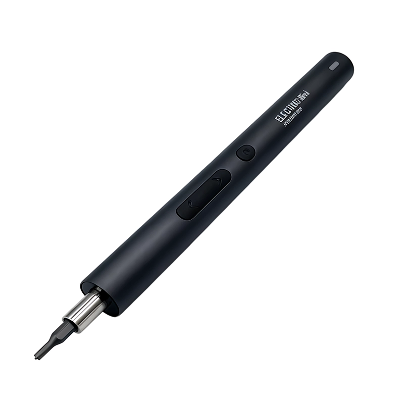
Remove power and follow the aircraft maker’s battery and service precautions. Lock or support the gimbal without forcing its travel and photograph every cable route. Preparation should also include a clear place for the driver when it is not in use and a separate place for removed hardware. This prevents the tool, bit or customer screw from migrating into the working assembly. If the task exposes a board, battery, cable, seal, optical surface or calibrated structure, define when the powered tool leaves the work zone.
Confirm full bit seating by hand, then loosen with a short centered powered run. Short runs provide deliberate inspection points. After each meaningful stage, look at the screw head, bit and receiving structure. If the sound, position or resistance differs from expectation, release the control immediately. The objective is not to keep the motor running; it is to complete the joint without losing information about the condition of the product.
What is the step-by-step operating sequence?
1. Establish the service boundary
Remove power and follow the aircraft maker’s battery and service precautions. Confirm that the task is appropriate for the operator and that the product is in the required safe state. Identify anything that needs authorized service, special measurement, calibration or a different tool class. A bit that physically fits is not evidence that a repair is permitted or that the complete assembly can be restored correctly.
2. Build the fastener and workholding plan
Lock or support the gimbal without forcing its travel and photograph every cable route. Support the assembly near the fastener without blocking the operator’s view. Map hardware by location and stage, not only by color or apparent size. If two screws look alike, assume location still matters until the service information or measurement shows otherwise.
3. Qualify engagement before powered travel
Confirm full bit seating by hand, then loosen with a short centered powered run. The bit should enter to its designed depth without rocking or scraping adjacent features. Start slowly and keep axial alignment. When thread engagement is part of reassembly, use hand feedback first unless a validated work instruction explicitly defines another method.
4. Inspect before final assembly
Map screws and brackets in removal order so stack height and orientation remain visible. Clean the work area and account for every removed item. Check the screw recess, receiving thread, joint stack and nearby components. Do not conceal a cracked post, rotating insert, damaged seal or wrong-length fastener by applying more force.
5. Close and verify
Hand-start reassembly, inspect cable clearance, then complete the specified calibration and functional checks. Completion means more than seeing every screw installed. The enclosure or structure should sit naturally, the intended moving parts and cables should have clearance, and the product should pass the maker’s stated post-service checks. Record exceptions so the next repair starts with better information.
Which approach should a buyer or technician choose?
Short precision bit is characterized this way: Better clearance but may not reach recessed screws. By comparison, Extended precision bit is characterized this way: Adds reach but requires stricter straightness and side-clearance checks. Neither label is universally superior. The decision depends on the screw condition, access, receiving material, consequence of error, workload and evidence available for the exact product.
Favor control, visibility and verified reach over maximum speed; a slower workflow is preferable to loading a gimbal axis or trapping a flex cable. This recommendation keeps the application question separate from the marketing specification. Maximum speed, peak torque, battery size and accessory count can describe a platform, but they do not by themselves prove safe control at a particular screw. The accepted configuration should be demonstrated on representative hardware and documented so another operator can repeat it.

How should a buyer specify and approve the kit?
Evaluate a sample kit against the actual drone families serviced, including security profiles, extended-bit straightness, retention and case labels for field work. The RFQ should name target devices, fastener profiles and sizes, required working lengths, driver modes, charging pack-out, storage layout, manual languages and sample quantity. For every numerical or compatibility claim, ask what exact model, method and evidence supports it. Keep the approved sample and revision record connected to the purchase specification.
For electric screwdriver for drone gimbal repair, the sample review should connect appearance and controls to this recommendation: Favor control, visibility and verified reach over maximum speed; a slower workflow is preferable to loading a gimbal axis or trapping a flex cable. Review the installed bit, representative screw sequence, charging state, indicators, case, labels and manual in that context. Evaluate a sample kit against the actual drone families serviced, including security profiles, extended-bit straightness, retention and case labels for field work. Any change to the motor, battery, cable, bit map or insert must be assessed against this same task before a revised configuration enters production.
What common mistake should the workflow prevent?
The common mistake is allowing the gimbal to hang unsupported while the driver’s reaction twists a motor axis. Prevent it with a visible instruction and an observable stop condition. Telling an operator to “be careful” is not a process. Telling the operator which bit to use, where to place the screw, when to switch from hand to power and what condition requires a stop creates a repeatable decision.
Use field and return records to improve the electric screwdriver for drone gimbal repair workflow. Code the observed result of a long or misaligned bit can touch a cable or bearing, while mixed screws can change clearances and interfere with movement, the contributing setup and whether allowing the gimbal to hang unsupported while the driver’s reaction twists a motor axis was present, rather than merging everything into a generic tool complaint. A recurring pattern can then point to instruction, labeling, accessory choice, product design or supplier control without inventing a performance claim from an unverified report.
Practical buying recommendation
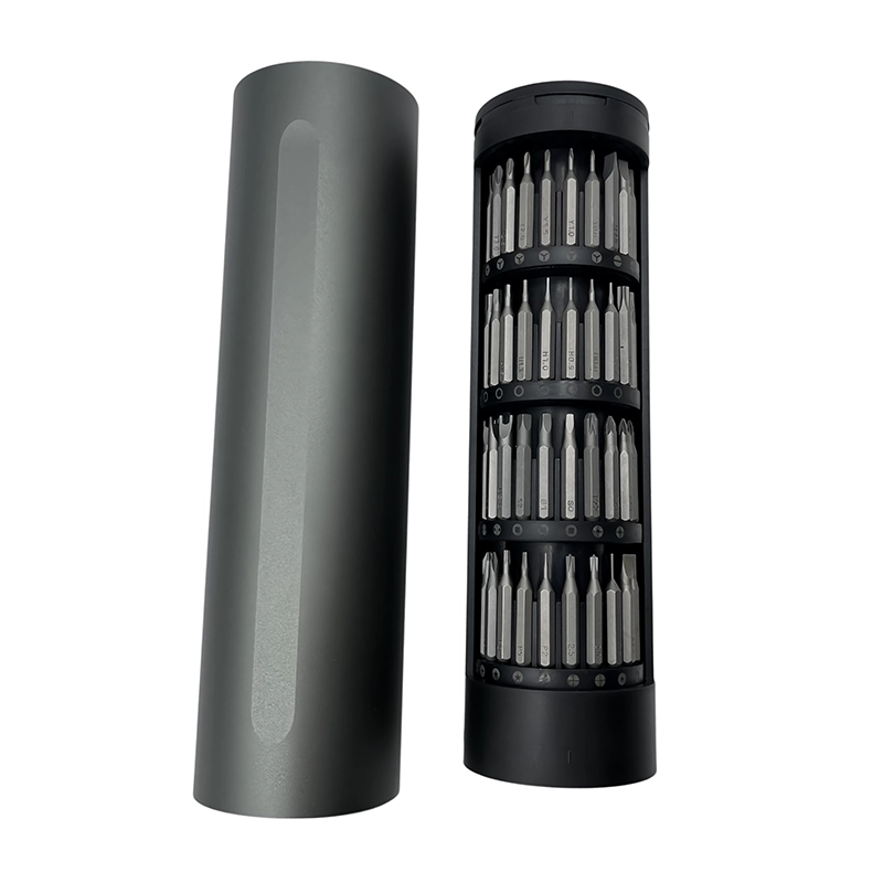
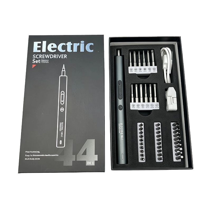
XOENAEN 44-in-1 electric screwdriver set is the real XOENAEN catalogue reference used for electric screwdriver for drone gimbal repair. Compare its current model record, bit layout and physical sample with removing gimbal covers or motor brackets where access is narrow and nearby flex cables, dampers and calibrated axes must not be loaded; this article does not turn that catalogue entry into universal compatibility or an unverified device result. Send the target device or joint list, project volume, market, packaging and the buyer requirement “Evaluate a sample kit against the actual drone families serviced, including security profiles, extended-bit straightness, retention and case labels for field work.” for a model-level recommendation.
Short precision bit compared with Extended precision bit
| Approach | Best use | Primary control |
|---|---|---|
| Short precision bit | Better clearance but may not reach recessed screws | match Torx, hex or Phillips profiles to the exact airframe service information |
| Extended precision bit | Adds reach but requires stricter straightness and side-clearance checks | select bit length that reaches the screw without contacting the gimbal frame |
- Define the exact customer question: What should technicians check before using an electric screwdriver on a drone gimbal?
- Document the real application: removing gimbal covers or motor brackets where access is narrow and nearby flex cables, dampers and calibrated axes must not be loaded
- Verify the first technical control: match Torx, hex or Phillips profiles to the exact airframe service information
- Verify the second technical control: select bit length that reaches the screw without contacting the gimbal frame
- Approve the sample against XOENAEN 44-in-1 electric screwdriver set
- Record the bit map, charging pack-out, labels and change-control owner
- XOENAEN 44-in-1 electric screwdriver set →
- How to choose a precision electric screwdriver →
- Electric screwdriver torque guide →
- XOENAEN OEM and ODM process →
- Manufacturing and quality control →
- Read the related electric-screwdriver-private-label-repair-kit guide →
- Continue with the electric-screwdriver-action-camera-housing-service topic →
- How XOENAEN presents quality evidence →
Can an electric screwdriver damage a drone gimbal?
Yes. Side load, wrong reach or uncontrolled seating can affect delicate mechanical and electrical parts, so stabilize the assembly and use documented settings.
Do drone gimbals need extended bits?
Some recessed fasteners do, but reach must be checked against cable and frame clearance on the exact model.
Should gimbal screws be thread-locked automatically?
No. Use only the retention method specified by the device maker for that location.
Why map gimbal screws?
A map prevents length and bracket-location errors that can restrict movement or damage internal features.
What should be checked after reassembly?
Check free travel, cable clearance, correct fastener locations and the manufacturer’s required calibration and functional sequence.