For clean 3D printed camera cable strain relief, first identify a bridge ridge or support scar at the channel entry and protect cable bend radius, insulation clearance, retaining tabs and mounting-hole alignment. Start with a narrow safe-edge scraper and a backed abrasive strip; use a slim rotary point used only at a mapped internal high spot only when access requires it. Control cable diameter, bend radius, wall thickness, tool approach and contamination control. Stop when a retaining tab flexes, a channel wall thins or the cable reference begins to bind. Release the part only when the specified cable routes without abrasion, holds under the intended light service load and clears all hardware.
clean 3D printed camera cable strain relief
clean 3D printed camera cable strain relief is a controlled post-processing workflow that removes a bridge ridge or support scar at the channel entry from a printed camera-rig bracket, sensor housing or small electronics mount with a cable channel while preserving cable bend radius, insulation clearance, retaining tabs and mounting-hole alignment.
How can a cable strain-relief channel be cleaned without damaging the cable's bend path? This guide uses a printed camera-rig bracket, sensor housing or small electronics mount with a cable channel as a practical post-processing case. It does not assume that a rotary pen is the first answer for every polymer or geometry: the material supplier, approved accessory limit, workholding and representative sample control the final process.
What should be mapped before material is removed?
Start by photographing the condition and identifying a bridge ridge or support scar at the channel entry. Mark the smallest area that actually interferes with the next operation. On a printed camera-rig bracket, sensor housing or small electronics mount with a cable channel, the protected features are cable bend radius, insulation clearance, retaining tabs and mounting-hole alignment. A smoother looking part can still be a reject when its fit, load path or visible geometry has changed.
Which finishing method should be the reference?
a narrow safe-edge scraper and a backed abrasive strip is the reference method because it gives immediate tactile feedback. Make a short trial on an equivalent defect, clean the area and compare it with an untouched reference. The aim is to confirm the contact map before a powered accessory repeats the correction more quickly.
When does a rotary pen add practical value?
a slim rotary point used only at a mapped internal high spot can be useful when the defect is inside a recess or an awkward corner. It is a local-access method, not a substitute for controlled machining or a reason to abrade an entire feature. Use a representative coupon first and keep the accessory moving through short, inspectable contacts.
How should the workpiece be supported?
Use a fixture that supports the bracket at its mounting faces while leaving the channel open. This limits vibration and keeps the operator able to see the contact zone. Check that the part cannot rotate into the accessory, that dust does not hide the defect and that the fixture does not preload thin printed features. Recheck the setup after every material or part-revision change.
Which variables should be recorded on the first article?
Record cable diameter, bend radius, wall thickness, tool approach and contamination control, together with print material, orientation, part revision, accessory identity, fixture and start/end photographs. A written record should tell the next operator where contact is allowed, which area is no-touch and which gauge or mating item proves the correction has not changed the design.
What is the controlled pass sequence?
For clean 3D printed camera cable strain relief, inspect, mark, support, make one light pass, stop, remove debris and inspect again. Repeat only if the marked defect remains. If the same artifact appears across multiple prints, investigate the print process, part orientation or design rather than converting unlimited hand rework into the normal production method.
Which sign means the operation must stop?
Stop immediately when a retaining tab flexes, a channel wall thins or the cable reference begins to bind. Do not compensate with higher speed or pressure. Clean the part and compare it with the starting image, then decide whether a different hand method, a new fixture, a reprint or an upstream correction is the responsible next step.
How should the result be accepted?
The release condition is that the specified cable routes without abrasion, holds under the intended light service load and clears all hardware. Inspect under repeatable light and, where function matters, use the actual mating component or a documented gauge. Cosmetic improvement alone is not proof that a printed functional feature still works as designed.
What should a buyer specify in a finishing-tool brief?
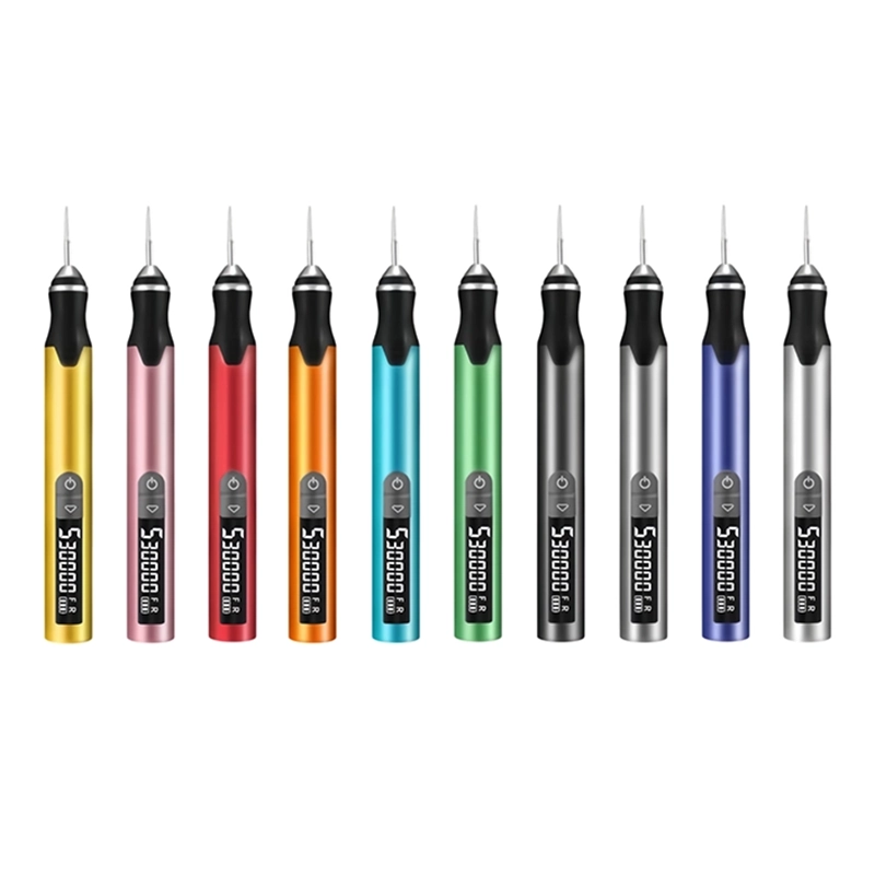
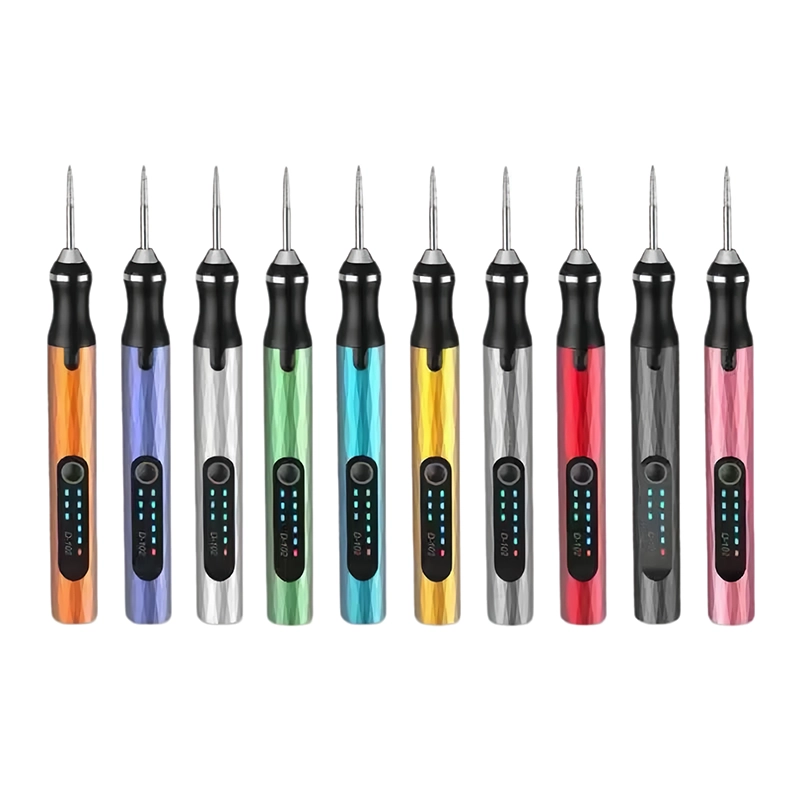
For clean 3D printed camera cable strain relief, specify the printed material, real defect, protected dimensions, fixture, accessory interface, desired pack-out, target market, sample quantity and acceptance check. The XOENAEN D-102 cordless engraving pen is a first-party XOENAEN catalogue reference; it does not establish a universal setting or outcome for every printed part. Qualify the proposed configuration on the buyer's own representative sample before making customer-facing claims.
Choose the least aggressive controlled method
| Method | Best use | Risk to manage |
|---|---|---|
| a narrow safe-edge scraper and a backed abrasive strip | Map the defect and establish a tactile reference | Slow access or unintended edge contact |
| a slim rotary point used only at a mapped internal high spot | Reach a mapped local obstruction | a retaining tab flexes, a channel wall thins or the cable reference begins to bind |
| Reprint or upstream correction | A defect repeats or critical geometry is affected | Requires a documented new sample |
- Map a bridge ridge or support scar at the channel entry before choosing an accessory.
- Protect cable bend radius, insulation clearance, retaining tabs and mounting-hole alignment.
- Support with a fixture that supports the bracket at its mounting faces while leaving the channel open.
- Control cable diameter, bend radius, wall thickness, tool approach and contamination control.
- Stop when a retaining tab flexes, a channel wall thins or the cable reference begins to bind.
- Approve only when the specified cable routes without abrasion, holds under the intended light service load and clears all hardware.
- XOENAEN D-102 cordless engraving pen →
- 3D print finishing tools guide →
- Rotary tools and 3D print finishing hub →
- Related guide: open 3d printed cable channel without thinning wall →
- Related guide: tune 3d printed cable chain end connector →
- Plan an OEM or ODM tool project →
- Continue with the clean-3d-printed-drawer-slide-spacer-shims topic →
- Related guide: 3D print finishing quality checklist before painting or assembly →
What should be checked before you clean 3D printed camera cable strain relief?
Confirm a bridge ridge or support scar at the channel entry is outside the approved geometry, then protect cable bend radius, insulation clearance, retaining tabs and mounting-hole alignment. Photograph the starting condition and choose the inspection or mating reference before any material is removed.
Why is workholding important for clean 3D printed camera cable strain relief?
Use a fixture that supports the bracket at its mounting faces while leaving the channel open. Stable support limits vibration and helps prevent unplanned contact with cable bend radius, insulation clearance, retaining tabs and mounting-hole alignment. It also makes the first-article method reproducible.
When should a rotary pen be used for clean 3D printed camera cable strain relief?
a slim rotary point used only at a mapped internal high spot is useful only after the contact is mapped and a hand reference is understood. Test the material, accessory and part geometry on a representative coupon before approving it for repeated work.
What is the stop signal for clean 3D printed camera cable strain relief?
Stop when a retaining tab flexes, a channel wall thins or the cable reference begins to bind. Clean and inspect instead of increasing speed or pressure; removed geometry cannot be restored by later polishing.
What should an OEM buyer provide for clean 3D printed camera cable strain relief?
For clean 3D printed camera cable strain relief, provide the part revision, material, defect photo, protected features, acceptance gauge or mating part, target market, pack-out and required sample evidence. This allows the tool and accessory proposal to be evaluated against the real work.