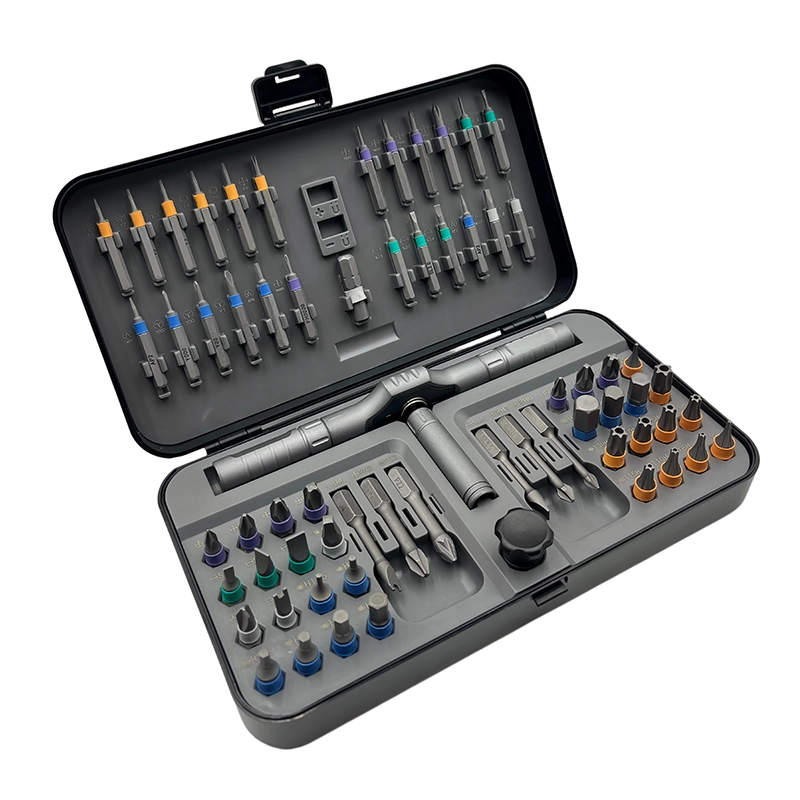
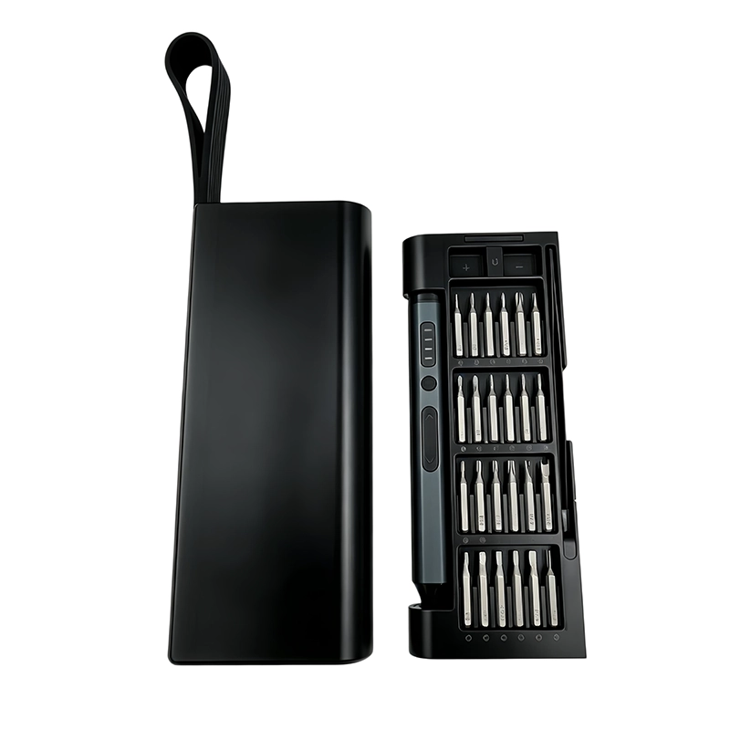
Measure electric screwdriver runout with a clean holder and at least two known-straight reference bits. Seat each bit consistently, rotate at a low speed and observe or measure at a fixed distance. Reseat and swap bits to separate accessory error from holder or drive error. Use a product-specific acceptance rule; no universal runout number fits every bit length and application.
Installed-bit runout
Radial variation measured at a defined point on an installed bit while the screwdriver rotates under a stated speed, seating, fixture and measurement method.
What does an electric screwdriver runout test measure?
An electric screwdriver runout test measures radial movement at a defined point on an installed bit while the system rotates. The observed result contains the bit's straightness, holder geometry, seating condition, interface clearance, shaft and bearing behavior, and the chosen measurement distance. That is why runout should be reported as an installed-system result under a written method, not as a vague judgment that the motor or bit looks straight.
What causes visible bit wobble?
Visible wobble can come from a bent bit, burr, contamination, incomplete seating, worn holder, interface clearance, shaft error, bearing condition or a combination of those sources. A long bit makes small angular errors easier to see at the tip. High speed can exaggerate the visual impression and blur the observation. Start by preserving the tool and bit condition, then isolate one contributor at a time rather than attributing all motion to the driver.
How should the tool and reference bits be prepared?
Use at least two known-straight reference bits of documented profile and length. Inspect them for bends, damaged drive surfaces and tip wear. Clean the holder and bit interface with a method that does not push debris into the tool. Seat each bit using the same insertion procedure and confirm retention. Mark a fixed observation or measurement distance from the holder because movement at the tip increases with distance.
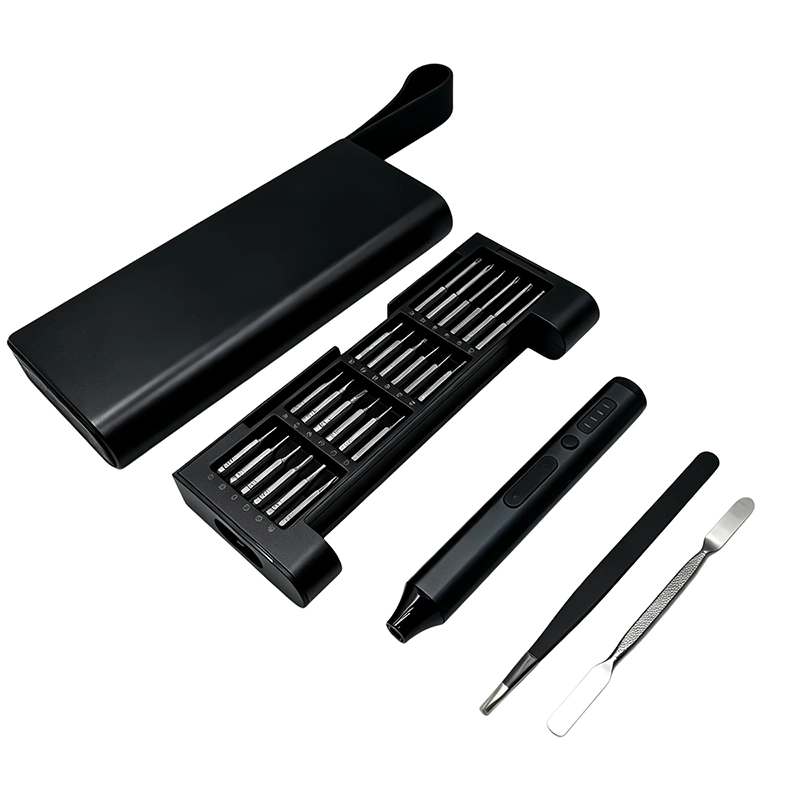
How is a visual screwdriver wobble test performed?
Run the driver at the lowest practical speed and observe from a fixed side position against a stable reference line. Keep the tool supported without loading the bit. Reseat the first reference bit, rotate its orientation if the interface allows, and repeat with the second bit. A visual screen is useful for obvious orbiting, inconsistent seating or a damaged accessory, but it is operator-dependent and should not be used to invent a quantitative tolerance.
How should instrumented runout measurement be set up?
Choose equipment appropriate to the small expected movement and bit geometry, then define the fixture, contact point or sensing method, measurement distance, rotation speed, tool orientation, sample count and data capture. Confirm instrument status and fixture stability before measuring product samples. Record individual readings and the installed bit. If contact force deflects a thin bit or the fixture shifts, stop and correct the method before interpreting the result.
How can fixture and observation errors imitate runout?
A support that flexes, a clamp that touches the rotating holder, an angled camera view or an unstable reference line can create apparent motion that does not belong to the installed tool stack. Check the fixture with the driver stopped, then repeat the observation after removing and reinstalling the tool without changing the bit. For optical review, lock the camera position, focus and lighting rather than following the moving tip by hand. For a contact method, confirm that the probe force does not bend the working length. Record any setup correction as part of the method revision instead of silently mixing results from different arrangements.
Why must bit length and measurement distance be normalized?
The same small angular displacement produces more visible tip travel as the observation point moves farther from the holder. A result taken near the drive end therefore cannot be compared directly with one taken at the tip of a longer bit. Define the bit profile, total length, exposed working length and exact distance from a repeatable tool feature. If several bit lengths matter to the application, report them as separate configurations rather than averaging them together. This normalization makes supplier samples, pilot lots and later production checks comparable without pretending that one reading describes every accessory in the set.
How can a buyer separate bit, holder and drive effects?
First compare two reference bits in the same driver. If the motion follows one bit, inspect that accessory. If both bits show similar motion, clean and reseat them, then inspect holder retention and side play. Where a controlled comparison tool or holder is available, swap one element at a time. Record each configuration. Replacing several parts at once may make the symptom disappear, but it does not identify the source or support corrective action.
How should repeat observations and orientation changes be interpreted?
Repeat readings show whether the installed condition is stable enough to evaluate, while orientation changes help locate a contributor. Mark the bit drive end, reseat it through the allowed orientations and keep the same fixture and measurement point. If the high point follows the marked bit, investigate that bit. If it remains tied to the holder position across verified bits, inspect the interface and drive assembly. If the pattern changes after every seating, retention or contamination may be involved. These are diagnostic patterns, not automatic pass or fail rules; the agreed acceptance method still governs the decision.
What is acceptable runout for an electric screwdriver?
There is no universal public runout value that fits every precision screwdriver, bit length and fastener. The limit should come from the intended screw, access, working length, risk of cam-out and the agreed measurement method. A visual screen may use an observable no-orbit rule for obvious defects; a quantitative OEM limit needs a unit, distance, speed, fixture, sample plan and acceptance boundary. Do not publish a number that has not been verified for the exact configuration.
Why should bit quality be checked before the driver is rejected?
Straightness, drive-end dimensions, burrs, coating build and working length all influence the installed result. Verify the reference bit separately and inspect its engagement in representative fasteners. Hardness does not prove straightness, and a straight bit does not prove correct tip fit. Keep bit-quality, runout and fastener-fit observations as related but distinct checks so the corrective action addresses the actual failure.
How should an OEM supplier hand off runout evidence?
The buyer and supplier should agree the application bit, working length, fastener access and measurement method before a sample is judged. A useful handoff package identifies which readings came from engineering samples, a pilot lot or production, and keeps the individual values beside the fixture and instrument records. It should also name who owns a retest when a reference bit is damaged or the fixture changes. For an OEM project, place the approved method, result template, sample identity and change triggers in the same controlled project record. That lets a later holder, shaft, bearing, bit-source or assembly change be reviewed against the original configuration instead of against an undocumented visual memory.
What belongs in an OEM runout record?
Record model and revision, tool and batch identity, bit identity and length, cleaning and seating method, observation distance, speed, fixture, equipment and status, repetitions, individual results, visual notes, acceptance rule and decision. Include a change trigger for the holder, shaft, bearing, bit source, interface dimensions or assembly process. Send the intended fasteners and working lengths with the inquiry so the sample method can be agreed before production.
Runout screening and measurement methods
| Method | Useful for | Limit |
|---|---|---|
| Fixed-position visual screen | Finding obvious orbit, bent bits or inconsistent seating | Operator-dependent and not a quantitative tolerance |
| Instrumented runout measurement | Comparing identified samples under a controlled method | Requires suitable equipment, fixture and defined contact point |
| Reference-bit substitution | Separating an accessory symptom from holder or drive behavior | Needs more than one verified straight bit and controlled reseating |
- Use two documented straight reference bits
- Clean and seat the interface consistently
- Fix speed, tool orientation and observation distance
- Separate visual screening from quantitative measurement
- Retain individual readings and configuration identity
- Set the acceptance boundary from the real fastener and working length
How is electric screwdriver runout measured?
Use a clean holder, known-straight installed bit, fixed measurement distance, defined low speed, stable fixture and suitable visual or instrumented method. Record the complete setup with each result.
What causes electric screwdriver bit wobble?
A bent bit, debris, incomplete seating, holder wear, interface clearance, shaft or bearing behavior can contribute. Isolate sources through cleaning, reseating and reference-bit substitution.
What is acceptable runout for an electric screwdriver?
Set a product-specific limit from the fastener, bit length, access and risk under one defined method. No universal value fits every precision screwdriver application.
Can a visual screwdriver wobble test approve an OEM tolerance?
It can screen obvious defects, but a quantitative limit requires a defined unit, observation point, speed, fixture, equipment, sample plan and acceptance rule.
Why should two reference bits be used?
If motion follows one bit, the accessory is suspect. If comparable motion remains across verified bits, inspect seating, holder and drive contributors.
Does bit hardness prove bit straightness?
No. Hardness, straightness and tip fit are separate characteristics and need separate checks tied to the same documented bit identity.